Appendix b: product specifications – B&B Electronics ZXT9-IOA-KIT - Manual User Manual
Page 61
Appendix B: Product Specifications
Manual Documentation Number: ZXTx-IO-x-4113m
55
A
A
p
p
p
p
e
e
n
n
d
d
i
i
x
x
B
B
:
:
P
P
r
r
o
o
d
d
u
u
c
c
t
t
S
S
p
p
e
e
c
c
i
i
f
f
i
i
c
c
a
a
t
t
i
i
o
o
n
n
s
s
Xtreme I/O Module Models:
ZXT24-IO-222R2
ZXT9-IO-222R2
Manual:
Electronic version of this manual, PDF available
CD-ROM disc:
Zlinx Manager
PDF of Zlinx Xtreme I/O User Manual
PDF of Quick Start guide
Operating Systems
supported:
Windows 2000/XP/Vista/7 (32 & 64 bit)
Dimensions:
3.23 x 3.15 x 3.35 in (82L x 80W x 85H mm)
Radio Properties
ZXT24-IO-222R2 (SR) Option:
Up to 300 ft indoors / 1 mile outdoors (Line Of Sight)
ZXT9-IO-222R2 (LR) Option:
Up to 3000 ft indoors / 14 miles outdoors (Line Of Sight)
Antennas:
For 2.4 GHz models: 4.25 inch Omni-directional rubber duck
antenna. PN: ZZ24D-ANT1
For 900 MHz models: 7.7 inch Omni-directional rubber duck
antenna. PN: ZXT9-ANT1
Receiver Sensitivity
ZXT24-IO-222R2;
ZXT24-RM
-102 dBm
ZXT9-IO-222R2
ZXT9-RM
-100dbm @ 115.2K
-110dbm @ 9600
LED Indicators
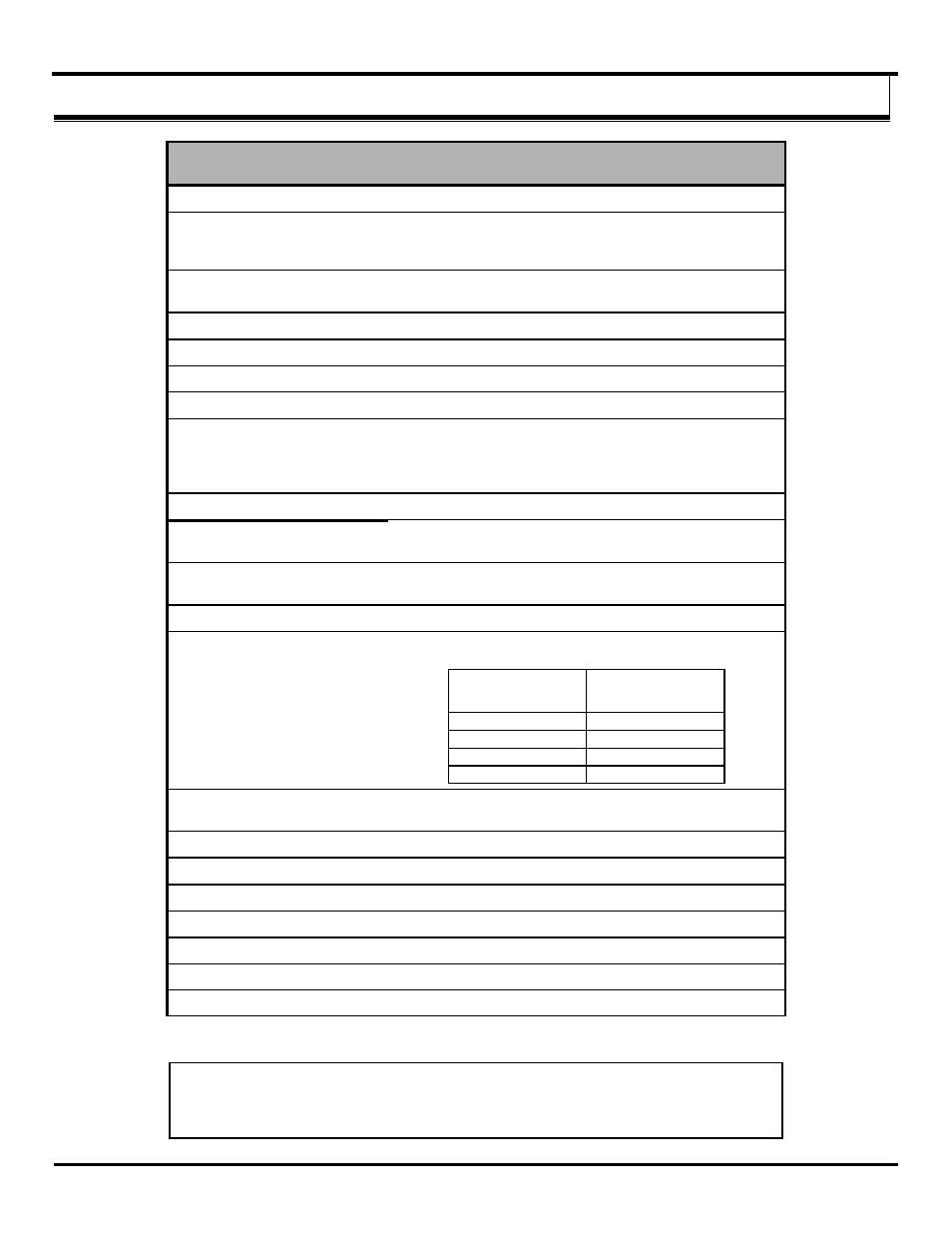
Receive Signal Strength
Indicator:
The RSSI indicator is 8 Green LEDs in a bar graph format
from Weak to Strong
LEDs Number
turned ON
Signal Strength
0
No signal
1-3
Weak
4-6
OK
7-8
Strong
RF Data Indicator:
Green LED (blinks with TD or RD data traffic, Off = no data
traffic)
Power Indicator:
Green LED, Blinks with Communication Failure
I/O Connectors:
Screw terminal
Digital Inputs
Voltage Range:
0 to 48 VDC
Low Voltage (0):
1.0 VDC maximum
High Voltage (1):
Greater than 1.0 VDC
Pull up/down current:
38uA
Frequency Input: Two DI inputs per module software selectable as Counters, 0 to
20 kHz range (do NOT exceed more than 20 kHz)