Troubleshooting, Esting, Igital and – B&B Electronics ZXT9-IOA-KIT - Manual User Manual
Page 57: Nalog
Troubleshooting
Manual Documentation Number: ZXTx-IO-x-4113m
51
7
7
.
.
T
T
r
r
o
o
u
u
b
b
l
l
e
e
s
s
h
h
o
o
o
o
t
t
i
i
n
n
g
g
This section is designed to help you answer some of the more common questions asked regarding installation and
configuration of Zlinx Xtreme I/O.
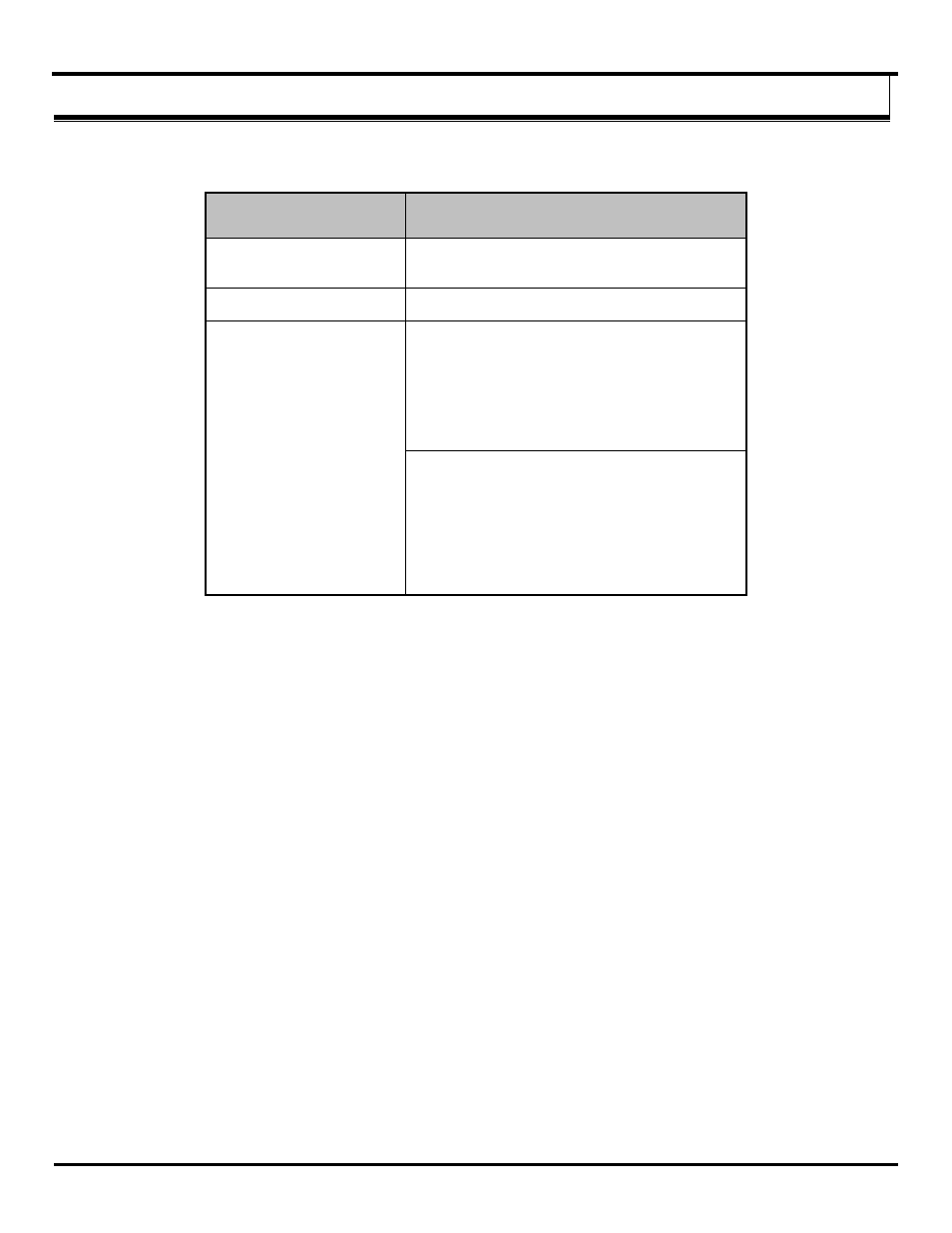
Problem
Causes and Resolutions
Power LED is not on
Insure that power connections to the
Xtreme Module are properly connected and correct
power voltage and current is applied.
Power LED is blinking
No wireless connection established
RSSI
– No Signal (No LEDs
ON) Or Weak Signal (3 or
less LEDs ON)
and
Wireless LED intermittently
blink:
Firmware does not match
The firmware for all Xtreme Modules must match.
The firmware revision number may be viewed on
the information tab of the configuration software.
See section 6.2
“Updating Zlinx I/O Firmware”.
If the firmware does not match, then update the
firmware with the Zlinx I/O Firmware Updater
software.
No Peer-to-Peer communication link
The communication link is not established. Verify
that all parameters in the configuration tab in the
programming software are correct.
Make sure that there are no obstacles in the path of
the wireless transmission.
Figure 7-1 Problem-Cause-Resolution Table
7.1 Testing Digital and Analog I/O
There are simple tests that can be performed to confirm the functionality of the hardware and wiring configurations. The
following diagrams can be used to aid in diagnosing problems with device connections.
To properly connect a Digital Output to the Digital Input of your data acquisition equipment, you need to know whether the
output is “sinking” or “sourcing”. A “sinking” output acts simply as a switch to ground and may be referred to as a dry contact.
A “sinking” output requires an additional power source for connected devices or an internal pull up resistor. A “sourcing”
output supplies the voltage itself and requires a pull down resistor between the digital input or output and ground to provide the
low voltage condition when the output is turned off.
To test devices you need to create a working system. For the purpose of the test create a system in Peer-to-Peer mode.
Create two systems: System-1 consisting of a Xtreme Module, System-2 consisting of a Xtreme Module. Both Xtreme
Modules must be the same model. Analog and Digital Input
signals connected to AI’s and DI’s on one system appear on the
corresponding AO’s and DO’s on the other system and vice versa.