Modbus i/o addressing, Modbus function codes, Modbus i/o registers – B&B Electronics ZXT9-IOA-KIT - Manual User Manual
Page 43: Digital (relay) outputs, 3 modbus i/o addressing
Configuration & Operation
Manual Documentation Number: ZXTx-IO-x-4113m
37
6.1.3 Modbus I/O Addressing
In Modbus mode, Digital and Analog Input information from the Zlinx Xtreme I/O inputs is stored in the Zlinx Xtreme I/O
memory in Modbus format and sent across the link to the Modbus modem. Digital and Analog Output information is sent from
the Modbus modem to the Zlinx Xtreme I/O in Modbus format, which set the outputs to the desired states/levels.
To use Modbus mode successfully, an understanding of the Zlinx Xtreme I/O memory map assignments and Function Codes
is necessary.
What is a Modbus Map?
A Modbus Map is simply a list for an individual slave device that defines:
What the data is (ex. pressure or temperature readings).
Where the data is stored (which tables and data addresses).
How the data is stored (data types, byte and word ordering).
Some devices are built with a fixed map that is defined by the manufacturer, while other devices allow the operator to
configure or program a custom map to fit their needs.
6.1.3.1 Modbus Function Codes
The function code in the Master device query tells the addressed slave device what kind of action to perform. The data bytes
contain any additional information that the slave will need to perform the function.
The following Modbus function codes are supported:
Function 1: Read DO Status
Function 2: Read DI’s
Function 3: Read AO Status
Function 4: Read AI’s
Function 5: Write to Single DO (firmware v2.0 or higher)
Function 6: Write to Single AO
Function 15: Write to Multi DO’s
For example, function code 03 will query the slave to read holding registers and respond with their contents. The data field
must contain the information telling the slave which register to start at and how many registers to read.
6.1.3.2 Modbus I/O Registers
Messages sent between Zlinx Xtreme I/O and a Modbus modem use Modbus memory addresses to specify the type of
information being sent and where it is stored. In the Modbus addressing scheme, each type of I/O (DO, DI, AI, and AO) is
stored in a different section of the memory. The following sections show the memory register maps for different I/O types.
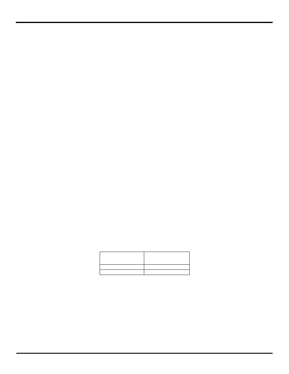
6.1.3.2.1 Digital (Relay) Outputs
There are 2 digital (Relay) outputs available in the I/O modules and their addressing is as follows:
Digital Outputs
Modbus Memory
Address
Digital Output 1
00001
Digital Output 2
00002
Fig 6-8 Digital (Relay) Output Memory Table
When the Zlinx Xtreme I/O receives a Modbus message to write
“1” to a discrete output register, the Zlinx Xtreme I/O module
turns ON its corresponding Digital Output.
As an example, to turn on the second Digital Output (DO2) on the Xtreme Module, the Modbus Master must set a value of 1 in
memory location 00002.