Input/output settings, Digital input configuration, 5 input/output settings – B&B Electronics ZXT9-IOA-KIT - Manual User Manual
Page 48
Configuration & Operation
42
Manual Documentation Number: ZXTx-IO-x-4113m
To configure the Zlinx Xtreme I/O Xtreme Module for Peer-to-Peer Slave Mode:
1. Select the Configuration tab.
2. Select the Peer-to-Peer Slave option button.
3. Set the Peer-to-Peer Slave address from 1 to 255. Please note the Peer-to-Peer Master address must also match.
4. Communication Failure Timeout. If within the predefined timeframe no data is coming from Peer-to-Peer Master, Slave
interprets it as a communication failure.
6.1.5 Input/Output Settings
Digital Inputs/Outputs and Analog Inputs/Outputs on Zlinx Xtreme I/O modules are configured from the Input/Output tab of the
Zlinx Manager. The first two Digital Inputs on any module can be configured as Discrete inputs or Counter inputs. Any
additional Digital Inputs operate as Discrete inputs only. Counter operation is only functional when the Zlinx Xtreme I/O is set
up in Modbus mode. Analog Inputs and outputs can be configured for voltage or current loop operation.
To configure Digital and Analog I/O, select the Input/Output tab.
An input tree appears listing all Modules in the system and the inputs/outputs available on them.
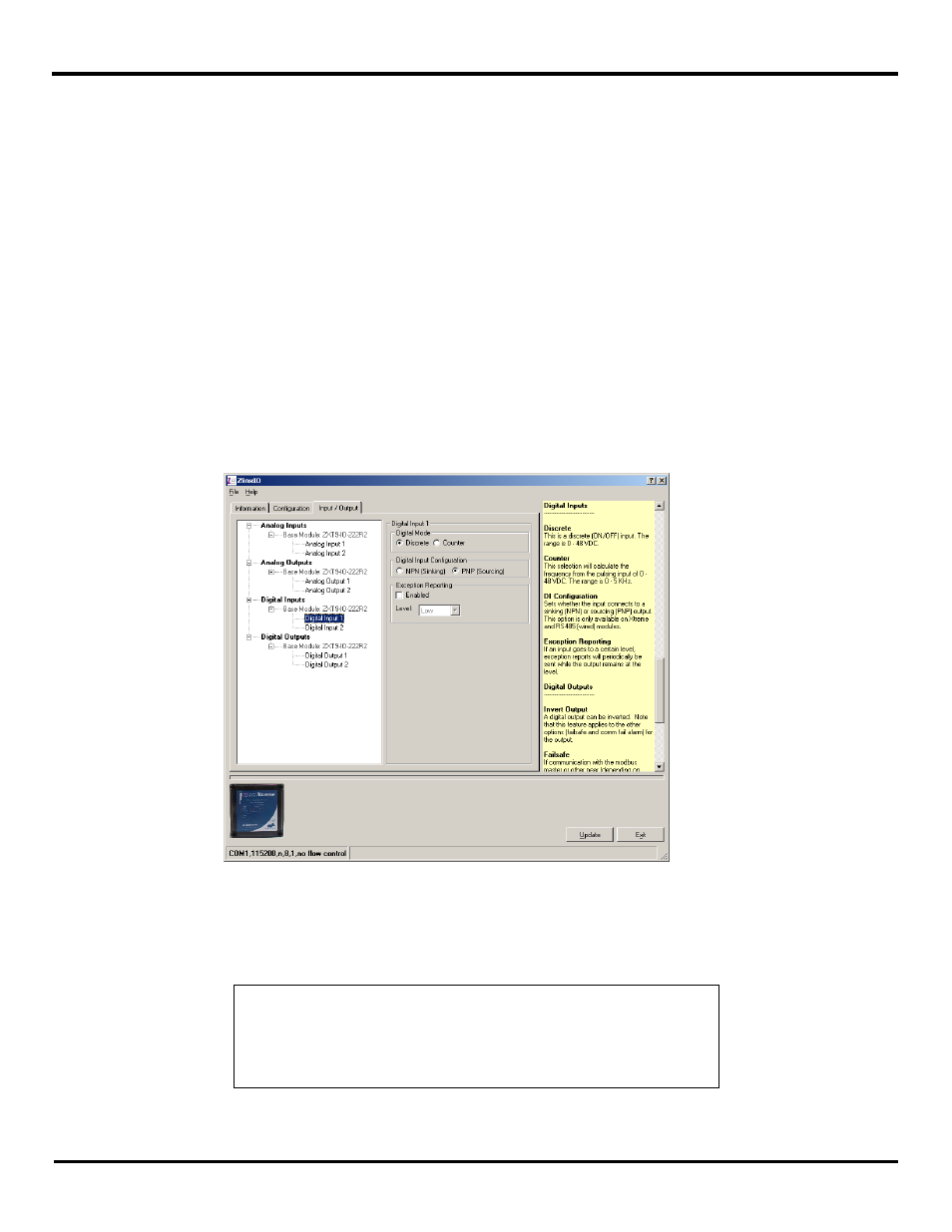
6.1.5.1 Digital Input Configuration
Fig 6-16 Digital Input Configuration
1. Select the Digital Input to be configured.
2. Select Discrete or Counter .
NOTE: See section -
2 associated with register Ox000B means
read from digital input register 10011
Function code 6 associated with register Ox000B means write to analog
3.
Select Digital Input type, PNP (Sourcing) or NPN (Sinking) based on the input connection
4.
For Exception Reporting, refer to Section 6.1.6.