Modbus mode settings, 2 modbus mode settings – B&B Electronics ZXT9-IOA-KIT - Manual User Manual
Page 42
Configuration & Operation
36
Manual Documentation Number: ZXTx-IO-x-4113m
Figure 36 shows the Zlinx Radio Modem configuration screen.
Click the ATKY Set button (for SR models, the ATEE command also needs to be set to 1). The Set Hex String box will appear.
Copy the key generated for the I/O module above into the box.
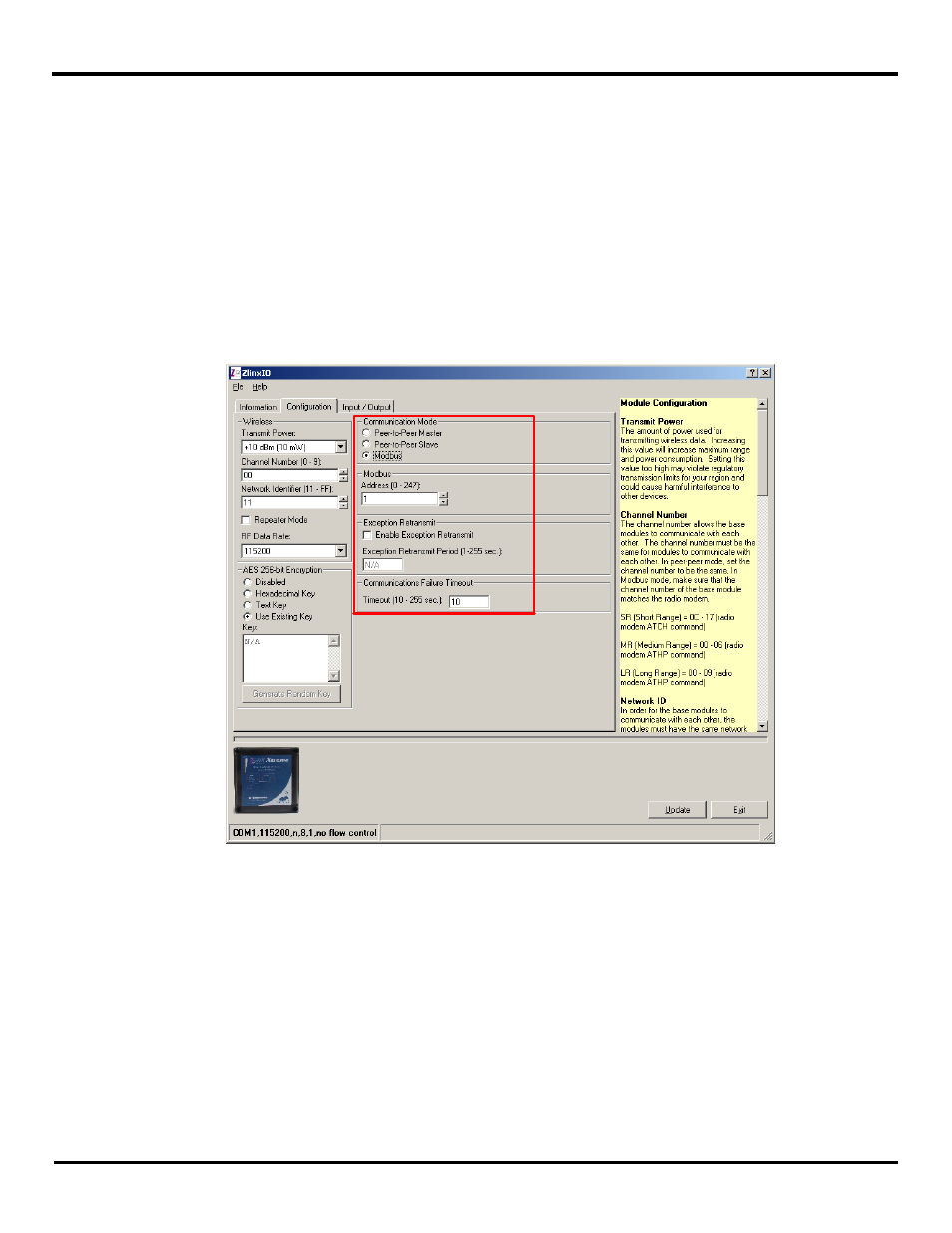
6.1.2 Modbus Mode Settings
When configured as a wireless Modbus node, Zlinx Xtreme I/O communicates with a Modbus RTU Master connected to a
Zlinx Wireless Modbus Modem and provides remote I/O functionality. The configuration screen for Modbus Mode is shown
below:
Fig 6-7 Modbus Mode Configuration
To configure the Zlinx Xtreme I/O for Modbus mode:
1. Select the Configuration tab.
2. Select the Modbus option button.
3. In the Modbus Address box, type the Modbus address to be used.
The allowable range of Modbus addresses is from 1 to 247. The default Modbus address is 1.
4. Set the value for the Communication failure timeout (in seconds). If within the predefined timeframe no data is coming from
Modbus Master (Modbus Radio Modem), the Zlinx I/O device perceives it as a communication failure