Digital inputs, Analog inputs, Analog outputs – B&B Electronics ZXT9-IOA-KIT - Manual User Manual
Page 44: Modbus frequency / counters inputs
Configuration & Operation
38
Manual Documentation Number: ZXTx-IO-x-4113m
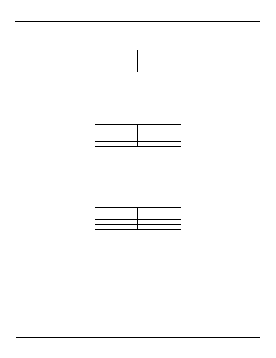
6.1.3.2.2 Digital Inputs
There are 2 digital inputs available in the I/O modules and their addressing is as follows:
Digital Outputs
Modbus Memory
Address
Digital Input 1
10001
Digital Input 2
10002
Fig 6-9 Digital Input Memory Table
When a digital input is ON, the I/O module sets the corresponding Modbus register as a ‘1’. Otherwise, the register value is ‘0’.
As an example, when the Digital Input (DO1) on the Xtreme Module goes ON, the Modbus register memory location 00002 will
be set to a value of 1.
6.1.3.2.3 Analog Inputs
There are two 16-bit analog inputs available in the I/O modules and their addressing is as follows:
Analog Inputs
Modbus Memory
Address
Analog Input 1
30001
Analog Input 2
30002
Fig 6-10 Analog Input Memory Table
The I/O module sets the register value based on the analog signal level.
As an example, for a 0-10V selection, when the analog input 1 is 5V, the memory location 30001 will read 32,768
Refer to Appendix F for analog data scaling.
6.1.3.2.4 Analog Outputs
There are two 16-bit analog inputs available in the I/O modules and their addressing is as follows:
Analog Outputs
Modbus Memory
Address
Analog Output1
40001
Analog Output 2
40002
Fig 6-11 Analog Output Memory Table
To set a 5 mA output current at analog output terminal 2, when a selection of 0- 20mA is made, the Modbus Master must set a
value of 16,384 in the memory location 40002.
Refer to Appendix F for analog data scaling.
6.1.3.2.5 Modbus Frequency / Counters Inputs
In Modbus mode, a Zlinx Xtreme I/O supports the two Digital Inputs in the following modes:
Frequency
Counters (Accumulators)