B&B Electronics ZXT9-IOA-KIT - Manual User Manual
Page 45
Configuration & Operation
Manual Documentation Number: ZXTx-IO-x-4113m
39
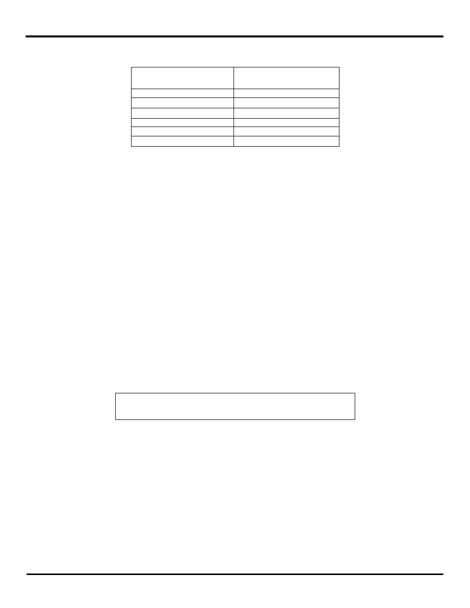
The table below show the Modbus register mapping for Frequency and Counter Inputs:
Frequency / Counter Data
Modbus Memory Address
DI1 - Frequency
40003
DI1
– Counter LS Register
40004
DI1
– Counter MS Register
40005
DI2 - Frequency
40006
DI2
– Counter LS Register
40007
DI2
– Counter MS Register
40008
Fig 6-12 Frequency/Counter Memory Table
Frequency
Registers 40003 & 40006 hold the frequency values if Digital Inputs 1 and 2 are configured as Frequency Inputs. Maximum
value of frequency is 20 KHz.
Flow meters typically generate a frequency based on the amount of fluid flowing through the sensor. The flow and respective
frequency varies on the manufacture and sensor. The frequency measurement is located in a separate Modbus holding
register and may not be written to. The frequency register is formatted in cycles/sec and requires the user to convert the
frequency to respective flow units
Counters
The most and least significant counter registers if Digital Inputs 1 and 2 are configured as Counter inputs are shown in Fig 6-
12. Both the most and least significant counter registers have a range of 0 to 9999 and rollover.
Time to save totals register counts down the number of seconds (from 300-0 seconds) until the Accumulators are saved
internally.
An example is a typical electric water meter that will generate a pulse per 1/10 gallon of water flowing through it. This type of
application is best used with the Modbus accumulators. The accumulators are broken down into two registers, most significant
count and least significant count. Both accumulators have a full count of 9999. When the least significant count exceeds
9999, it will increment the most significant count giving a total system count of 99,999,999.
The accumulators reside in the holding register map and maybe written to in order to reflect what a typical water meter may
have displayed on its display. There is also a holding register associated with the accumulators that indicates the number of
seconds before the accumulators are saved. The accumulator data is saved every ~5min.
NOTE:
“Appendix D: Modbus I/O Assignments” of this manual contains a list of
Modbus I/O assignments for the Zlinx Xtreme I/O.