Electrical installation, Ower, Iring – B&B Electronics ZXT9-IOA-KIT - Manual User Manual
Page 28
Electrical Installation
22
Manual Documentation Number: ZXTx-IO-x-4113m
4
4
.
.
E
E
l
l
e
e
c
c
t
t
r
r
i
i
c
c
a
a
l
l
I
I
n
n
s
s
t
t
a
a
l
l
l
l
a
a
t
t
i
i
o
o
n
n
Please see the Quick Start Guide for UL Class 1 Division 2 installation instructions.
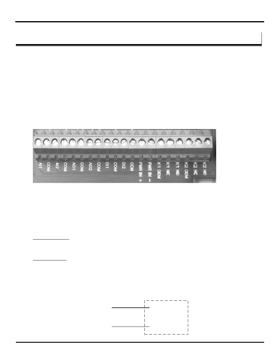
Both power and I/O signals are connected to the terminal block provided in the I/O module. The terminal block can be
accessed by removing the top cover and are provided at the bottom. Figure 4-1 shows the layout.
Consider the following requirements for cable connections and terminations.
Wiring Terminals
– Use Copper Wire Only, One Conductor per Terminal
Wire range: 10-28 AWG
Tightening Torque
– 0.5 to 0.6 Nm
Temperature Rating of field installed conductors - 105°C minimum, sized for 60°C ampacity
Figure 4-1 I/O Terminal Layout
4.1
Power Wiring
The radio modem requires a dc power supply from an external source. The permissible voltage range is 10 to 30 VDC. The
typical power consumption is as follows:
ZXT24-IO-222R2:
Type: 1.7W
Max: 4.5W
ZXT9-IO-222R2:
Type: 2.1W
Max: 6.8W
An optional IP67 power supply shown in Section 3.5.5.5 may be used.
Connect the positive and negative power leads to the Power In(+) and Power In (-) terminals on the terminal block.
PWR IN +
10-30 Vdc
(External Supply)
PWR IN -
V+
Com