Testing di, Testing do (relay o/p), Testing ai in “voltage” mode – B&B Electronics ZXT9-IOA-KIT - Manual User Manual
Page 58: Ainx com, 1 testing di, 2 testing do (relay o/p), 3 testing ai in “voltage” mode
Troubleshooting
52
Manual Documentation Number: ZXTx-IO-x-4113m
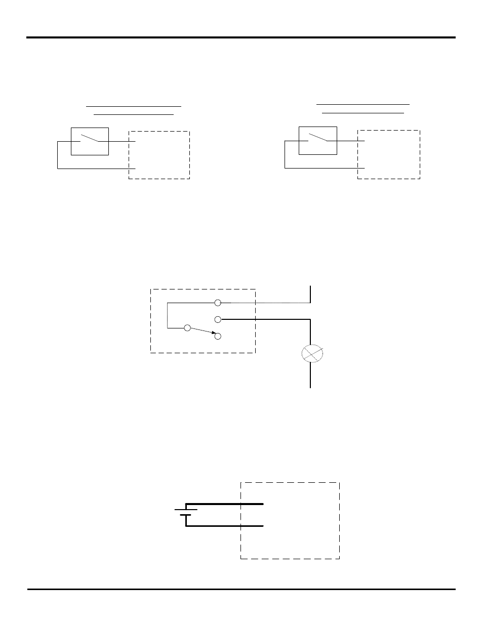
7.1.1 Testing DI
On System-1 connect one side of the switch to the DI on the Zlinx Xtreme I/O device and the other side of the switch to high or
ground depending on PNP or NPN configuration (see Figure 7-2). The LED corresponding to the DI should be ON
PWR IN +
DIx
(a) PNP (Sourcing) Input Wiring
with Internal Power Supply
DIx
(b) NPN (Sinking) Input Wiring
with Internal Power Supply
Com
Figure 7-2 Digital Input (Sourcing driver) wiring
7.1.2 Testing DO (Relay O/P)
To test a “relay” output the following can be performed. See “Appendix E: Zlinx Xtreme I/O Models and Features” to find out
which modules are relay. On System-1 on the corresponding Zlinx Xtreme I/O device connect a Light through COM and NO
contact of the relay output (see Error! Reference source not found.3). Make sure to check the polarity of the LED while
connecting it. On System-2 perform contact closure on the corresponding DI. The relay output should turn ON and the Light
should turn ON
NO
Com
NC
V+ / Ph
V- / N
Light
Figure 7-3 Relay Output Testing
7.1.3
Testing AI in “Voltage” Mode
Connect an AA battery (1.5 VDC) on the AI-1 on System-1 (see Fig 7-4) and a voltmeter on the corresponding AO-1 on
System-2. Make sure the polarity is correct while connecting the battery. Measure the voltage on the Analog Output on
System-2. It has to indicate 1.5 VDC.
AINx
COM
+
-
Figure 7-4 Analog Input wiring