Iring, Di wiring, I/o wiring – B&B Electronics ZXT9-IOA-KIT - Manual User Manual
Page 29: 1 di wiring
Electrical Installation
Manual Documentation Number: ZXTx-IO-x-4113m
23
Figure 4-2 Power Wiring Connection
4.2
I/O Wiring
The I/O module has the following options, PNP/NPN for digital I/Os and voltage/current for analog I/Os. The follow the wiring
recommendations help the user to connect the devices to the I/O module.
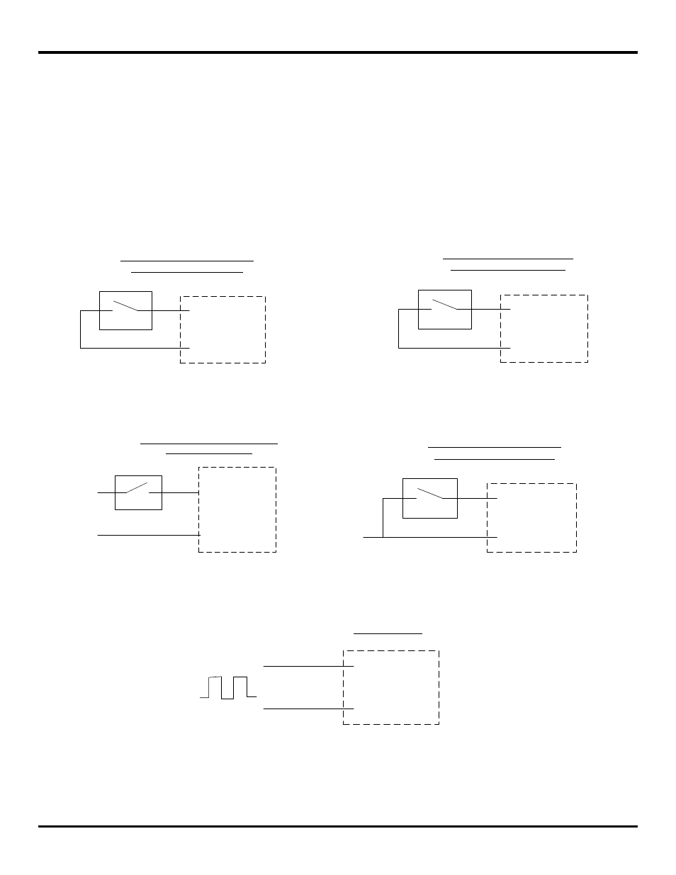
4.2.1 DI Wiring
The digital inputs are software configurable for PNP (sourcing) and NPN (sinking) connections. Each Input selection can be
independent of the other I/Os. PNP is chosen as the default setting. The configuration can be changed using the Manager
Software as explained in Chapter 6. The following diagrams show typical connection wiring for both PNP and NPN
connections with internal module power supply:
PWR IN +
DIx
(a) PNP (Sourcing) Input Wiring
with Internal Power Supply
DIx
(b) NPN (Sinking) Input Wiring
with Internal Power Supply
Com
Figure 4-3 Typical Digital Input Wiring for PNP and NPN connection types (with internal PS)
If an external power source is used for the digital input connections, the external power supply common should be connected
to the module power supply common. The diagrams below show the connection scheme:
+V
DIx
(c) PNP (Sourcing) Input Wiring with
External Power Supply
Com
Com
DIx
(d) NPN (Sinking) Input Wiring
with External Power Supply
Com
Com
Figure 4-4 Typical Digital Input Wiring for PNP and NPN connection types (with external PS)
A pulse/frequency input can be connected to the digital input as follows:
DIx
(e) Pulse Input
Com
Figure 4-5 Pulse Input Connection