Max2769b universal gps receiver, Ac electrical characteristics – Rainbow Electronics MAX2769B User Manual
Page 3
����������������������������������������������������������������� Maxim Integrated Products 3
MAX2769B
Universal GPS Receiver
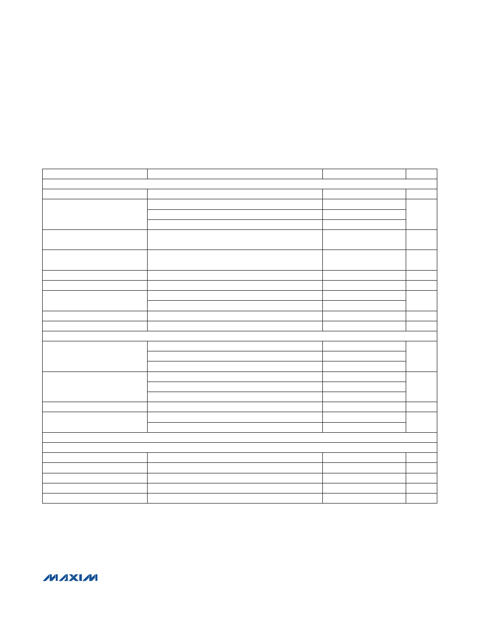
AC ELECTRICAL CHARACTERISTICS*
(MAX2769B EV kit, V
CC_
= 2.7V to 3.3V, T
A
= -40NC to +85NC, PGM = Ground. Registers are set to the default power-up states. LNA
input is driven from a 50I source. All RF measurements are done in the analog output mode with ADC bypassed. PGA gain is set
to 51dB gain by serial-interface word GAININ = 111010. Maximum IF output load is not to exceed 10kI||7.5pF on each pin. Typical
values are at V
CC_
= 2.85V and T
A
= +25NC, unless otherwise noted.) (Note 1)
PARAMETER
CONDITIONS
MIN
TYP
MAX
UNITS
CASCADED RF PERFORMANCE
RF Frequency
L1 band
1575.42
MHz
Noise Figure
LNA1 input active, default mode (Note 3)
1.4
dB
LNA2 input active, default mode (Note 3)
2.7
Measured at the mixer input
10.3
Out-of-Band 3rd-Order Input
Intercept Point
Measured at the mixer input (Note 4)
-7
dBm
In-Band Mixer Input Referred 1dB
Compression Point
Measured at the mixer input
-85
dBm
Mixer Input Return Loss
10
dB
Image Rejection
25
dB
Spurs at LNA1 Input
LO leakage
-101
dBm
Reference harmonics leakage
-103
Maximum Voltage Gain
Measured from the mixer to the baseband analog output
91
96
103
dB
Variable Gain Range
55
59
dB
FILTER RESPONSE
Passband Center Frequency
FBW = 00
4
MHz
FBW = 10
4
FBW = 01
9.27
Passband 3dB Bandwidth
FBW = 00
2.5
MHz
FBW = 10
4.2
FBW = 01
9.66
Lowpass 3dB Bandwidth
FBW = 11
9
MHz
Stopband Attenuation
3rd-order filter, bandwidth = 2.5MHz, measured at 4MHz offset
30
dB
5th-order filter, bandwidth = 2.5MHz, measured at 4MHz offset
40
49.5
LNA
LNA1 INPUT
Power Gain
19
dB
Noise Figure
0.83
dB
Input IP3
(Note 5)
-1.1
dBm
Output Return Loss
10
dB
Intput Return Loss
8
dB
*The parametric values (min, typ, max limits) shown in the Electrical Characteristics table supersede values quoted elsewhere in this data sheet.