Fractional clock divider, Figure 2. adc quantization levels for 2, Max2769b universal gps receiver – Rainbow Electronics MAX2769B User Manual
Page 15
���������������������������������������������������������������� Maxim Integrated Products 15
MAX2769B
Universal GPS Receiver
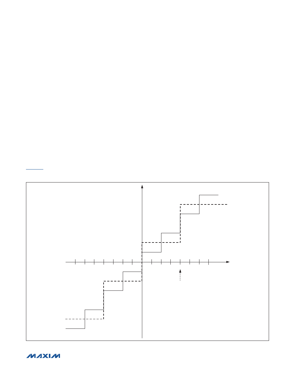
Figure 2. ADC Quantization Levels for 2- and 3-Bit Cases
ADC
The MAX2769B features an on-chip ADC to digitize the
downconverted GPS signal. The maximum sampling
rate of the ADC is approximately 50Msps. The sampled
output is provided in a 2-bit format (1-bit magnitude and
1-bit sign) by default and also can be configured as a
1-bit or 2-bit in both I and Q channels, or 1-bit, 2-bit, or
3-bit in the I channel only. The ADC supports the digital
outputs in three different formats: the unsigned binary,
the sign and magnitude, or the two’s complement format
by setting bits FORMAT in Configuration register 2. MSB
bits are output at I1 or Q1 pins and LSB bits are output at
I0 or Q0 pins, for I or Q channel, respectively. In the case
of 3-bit, output data format is selected in the I channel
only, the MSB is output at I1, the second bit is at I0, and
the LSB is at Q1.
illustrates the ADC quantization levels for 2-bit
and 3-bit cases and also describes the sign/magnitude
data mapping. The variable T = 1 designates the location
of the magnitude threshold for the 2-bit case.
ADC Fractional Clock Divider
A 12-bit fractional clock divider is located in the clock
path prior to the ADC and can be used to generate the
ADC clock that is a fraction of the reference input clock.
In a fractional divider mode, the instantaneous division
ratio alternates between integer division ratios to achieve
the required fraction. For example, if the fractional output
clock is 4.5 times slower than the input clock, an average
division ratio of 4.5 is achieved through an equal series
of alternating divide-by-4 and divide-by-5 periods. The
fractional division ratio is given by:
f
OUT
/f
IN
= L
COUNT
/(4096 - M
COUNT
+ L
COUNT
)
where L
COUNT
and M
COUNT
are the 12-bit counter val-
ues programmed through the serial interface.
1
2
3
4
5
6
7
-1
-2
-3
-4
-5
-6
-7
000
00
01
10
11
T = 1
111
110
101
100
001
010
011