Max2769b universal gps receiver, Pin description (continued) – Rainbow Electronics MAX2769B User Manual
Page 12
���������������������������������������������������������������� Maxim Integrated Products 12
MAX2769B
Universal GPS Receiver
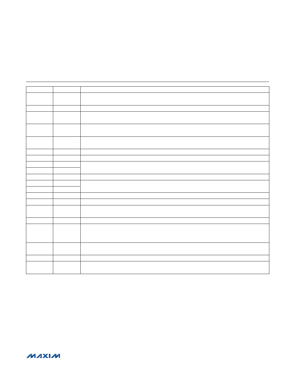
Pin Description (continued)
PIN
NAME
FUNCTION
10
CS
Chip-Select Logic Input of 3-Wire Serial Interface. Set CS low to allow serial data to shift in. Set CS
high when the loading action is completed.
11
V
CC_VCO
VCO Supply Voltage. Bypass to ground with a 100nF capacitor as close as possible to the pin.
12
CPOUT
Charge-Pump Output. Connect a PLL loop filter as a shunt C and a shunt combination of series R and
C (see the Typical Application Circuit).
13
V
CC_CP
PLL Charge-Pump Supply Voltage. Bypass to ground with a 100nF capacitor as close as possible to
the pin.
14
V
CCD
Digital Circuitry Supply Voltage. Bypass to ground with a 100nF capacitor as close as possible to the
pin.
15
XTAL
XTAL or Reference Oscillator Input. Connect to XTAL or a DC-blocking capacitor if TCXO is used.
16
CLKOUT
Reference Clock Output
17
Q1
Q-Channel Voltage Outputs. Bits 0 and 1 of the Q-channel ADC output or analog differential voltage
output.
18
Q0
19
V
CC_ADC
ADC Supply Voltage. Bypass to ground with a 100nF capacitor as close as possible to the pin.
20
I0
I-Channel Voltage Outputs. Bits 0 and 1 of the I-channel ADC output or analog differential voltage
output.
21
I1
22
N.C.
No Connection. Leave this pin unconnected.
23
V
CC_IF
IF Section Supply Voltage. Bypass to ground with a 100nF capacitor as close as possible to the pin.
24
IDLE
Operation Control Logic Input. A logic-low enables the idle mode, in which the XTAL oscillator is
active, and all other blocks are off.
25
LNA2
LNA Input Port 2. This port is typically used with an active antenna. Internally matched to 50I.
26
PGM
Logic Input. Connect to ground to use the serial interface. A logic-high allows programming to 8
hard-coded by device states connecting SDATA, CS, and SCLK to supply or ground according to
Table 3.
27
LNA1
LNA Input Port 1. This port is typically used with a passive antenna. Internally matched to 50I (see
the Typical Application Circuit).
28
N.C.
No connection. Leave this pin open.
—
EP
Exposed Pad. Ultra-low-inductance connection to ground. Place several vias to the PCB ground
plane.