Bi-directional port 4, Atar862-8 – Rainbow Electronics ATAR862-8 User Manual
Page 37
37
ATAR862-8
4589B–4BMCU–02/03
Table 7.
P5xM2, P5xM1
–
Port 5x Interrupt Mode/Direction Code
Bi-directional Port 4
The bi-directional Port 4 is a bitwise configurable I/O port and provides the external pins
for the Timer 2, SSI and the voltage monitor input (VMI). As a normal port, it performs in
exactly the same way as bi-directional Port 2 (see Figure 25). Two additional multi-
plexes allow data and port direction control to be passed over to other internal modules
(Timer 2, VM or SSI). The I/O-pins for SC and SD line have an additional mode to gen-
erate an SSI-interrupt.
All four Port 4 pins can be individually switched by the P4CR-register. Figure 25 shows
the internal interfaces to bi-directional Port 4.
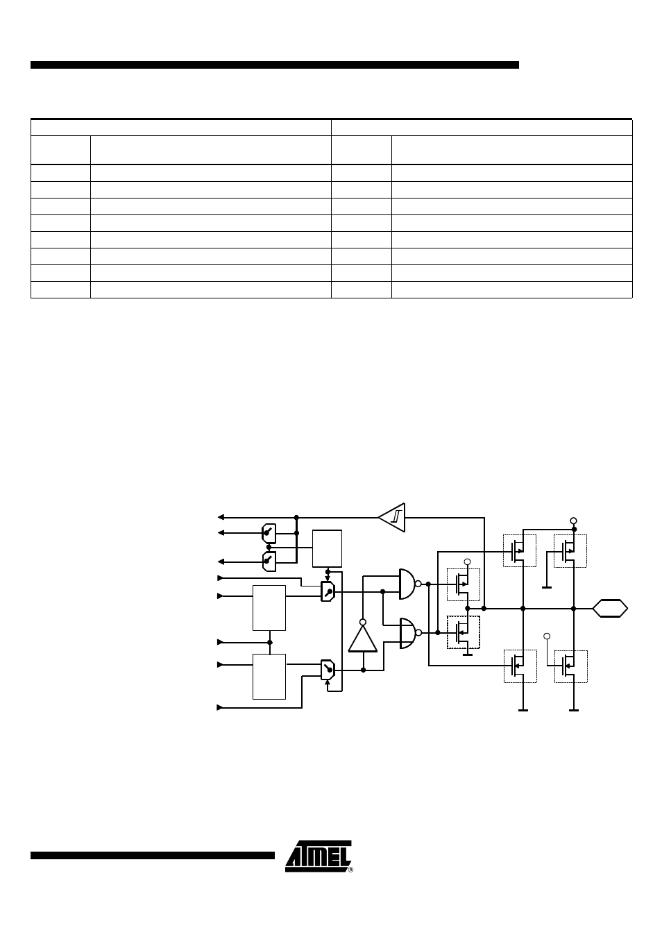
Figure 33.
Bi-directional Port 4 and Port 6
Auxiliary Address: "5"hex First Write Cycle
Second Write Cycle
Code
3 2 1 0
Function
Code
3 2 1 0
Function
x x 1 1
BP50 in input mode – interrupt disabled
x x 1 1
BP52 in input mode – interrupt disabled
x x 0 1
BP50 in input mode – rising edge interrupt
x x 0 1
BP52 in input mode – rising edge interrupt
x x 1 0
BP50 in input mode – falling edge interrupt
x x 1 0
BP52 in input mode – falling edge interrupt
x x 0 0
BP50 in output mode – interrupt disabled
x x 0 0
BP52 in output mode – interrupt disabled
1 1 x x
BP51 in input mode – interrupt disabled
1 1 x x
BP53 in input mode – interrupt disabled
0 1 x x
BP51 in input mode – rising edge interrupt
0 1 x x
BP53 in input mode – rising edge interrupt
1 0 x x
BP51 in input mode – falling edge interrupt
1 0 x x
BP53 in input mode – falling edge interrupt
0 0 x x
BP51 in output mode – interrupt disabled
0 0 x x
BP53 in output mode – interrupt disabled
Master reset
Q
V
DD
V
DD
BPxy
Mask options
*
*
PxDATy
I/O Bus
D
I/O Bus
I/O Bus
*
*
Switched
pull-up
Switched
pull-down
*
*
S
PxCRy
S
Q
D
PxMRy
POut
(Direction)
PDir
Intx
*
*
PIn
V
DD
Static
pull-up
Static
pull-down