3 register description, 1 mcucr – mcu control register, Figure 10-1 – Rainbow Electronics ATtiny43U User Manual
Page 59: Below, Figure 10-1. timing of pin change interrupts
59
8048B–AVR–03/09
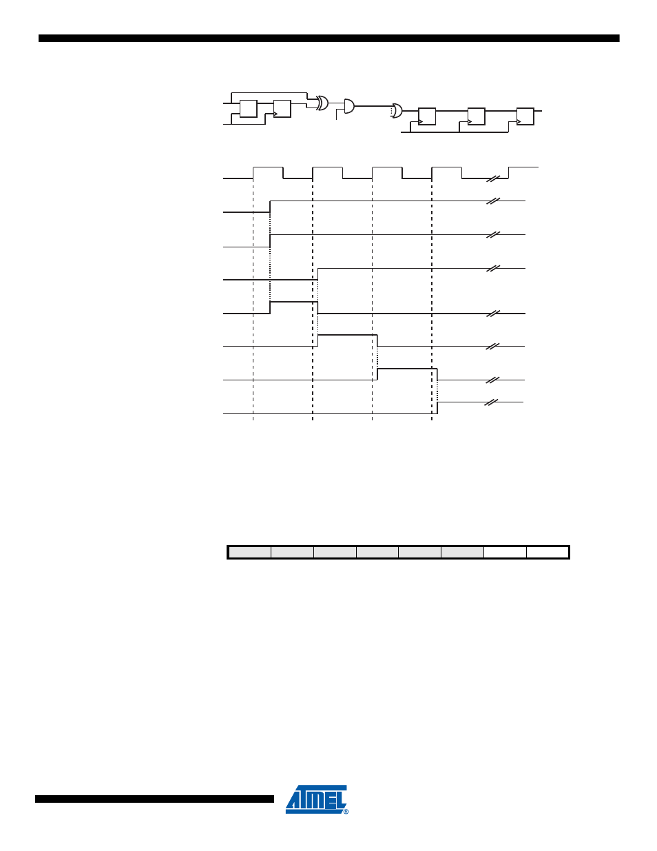
Figure 10-1. Timing of pin change interrupts
10.3
Register Description
10.3.1
MCUCR – MCU Control Register
The External Interrupt Control Register A contains control bits for interrupt sense control.
• Bits 1, 0 – ISC01, ISC00: Interrupt Sense Control 0 Bit 1 and Bit 0
External Interrupt 0 is activated by the external pin INT0 if the I-flag of SREG and the corre-
sponding interrupt mask are set. The level and edges on the external INT0 pin that activate the
interrupt are defined in
.
Edges on INT0 are registered asynchronously. Pulses on INT0 wider than the pulse width given
in
will generate an interrupt. Shorter pulses are not guaranteed to gen-
erate an interrupt.
clk
PCINT(0)
pin_lat
pin_sync
pcint_in_(0)
pcint_syn
pcint_setflag
PCIF
PCINT(0)
pin_sync
pcint_syn
pin_lat
D Q
LE
pcint_setflag
PCIF
clk
clk
PCINT(0) in PCMSK(x)
pcint_in_(0)
0
x
Bit
7
6
5
4
3
2
1
0
BODS
PUD
SE
SM1
SM0
BODSE
ISC01
ISC00
MCUCR
Read/Write
R/W
R/W
R/W
R/W
R/W
R/W
R/W
R/W
Initial Value
0
0
0
0
0
0
0
0