5 system and reset characteristics, 6 external interrupt characteristics, Will generate a reset – Rainbow Electronics ATtiny43U User Manual
Page 158: Attiny43u
158
8048B–AVR–03/09
ATtiny43U
20.5
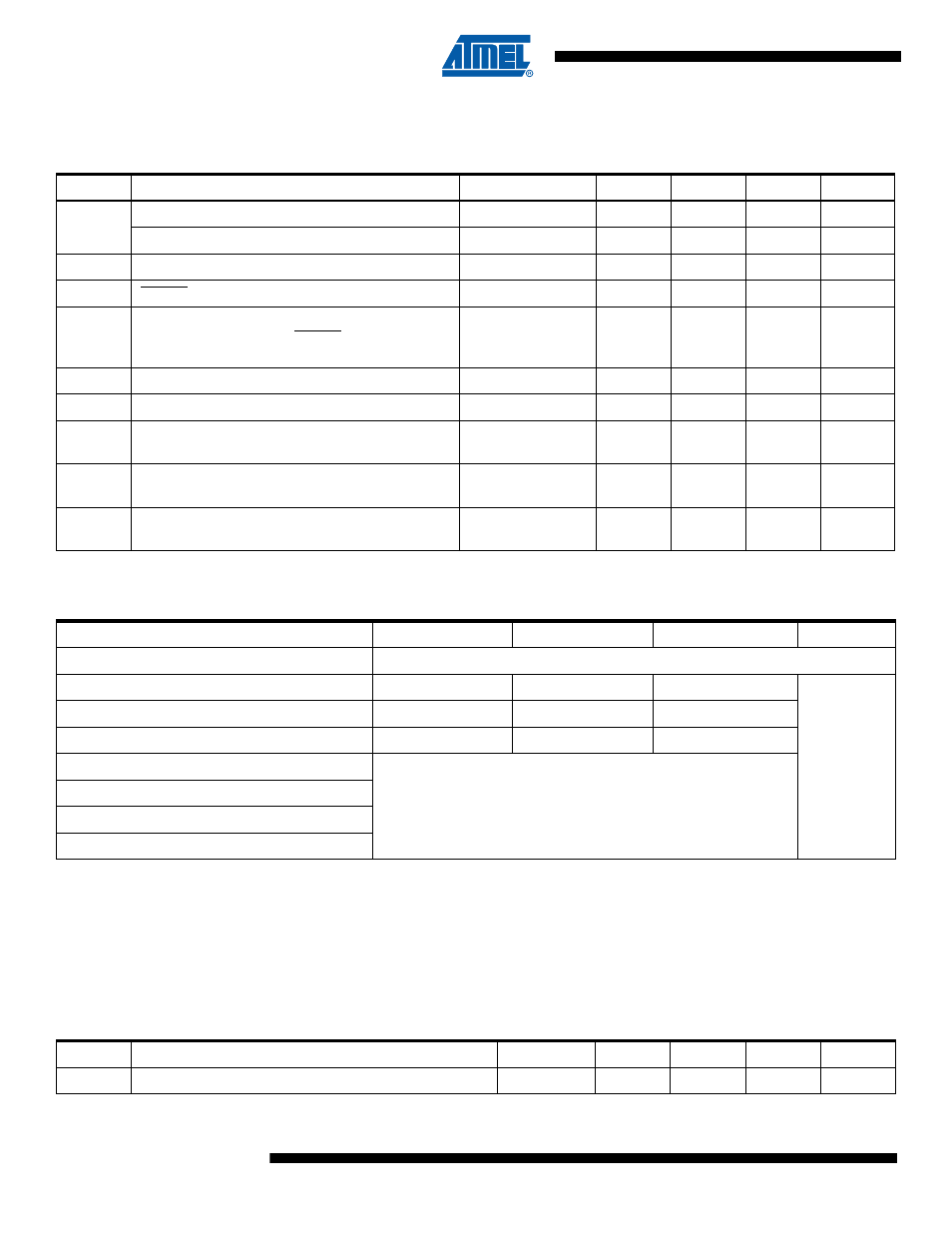
System and Reset Characteristics
Note:
1. The Power-on Reset will not work unless the supply voltage has been below V
POT
(falling)
Note:
1. V
BOT
may be below nominal minimum operating voltage for some devices. For devices where this is the case, the device is
tested down to V
CC
= V
BOT
during the production test. This guarantees that a Brown-out Reset will occur before V
CC
drops to
a voltage where correct operation of the microcontroller is no longer guaranteed.
20.6
External Interrupt Characteristics
Table 20-4.
Reset, Brown-Out and Internal Voltage Characteristics
Symbol
Parameter
Condition
Min
Typ
Max
Units
V
POT
Power-on Reset Threshold Voltage (rising)
T
A
= -40 - 85
°
C
1.1
1.4
1.6
V
Power-on Reset Threshold Voltage (falling)
T
A
= -40 - 85
°
C
0.6
1.3
1.6
V
V
PSR
Power-On Slope Rate
T
A
= -40 - 85
°
C
0.01
V/ms
V
RST
RESET Pin Threshold
0.2 V
CC
0.9 V
CC
V
t
RST
Minimum pulse width on RESET Pin
V
CC
= 1.8V
V
CC
= 3V
V
CC
= 5V
2000
700
400
ns
V
HYST
Brown-out Detector Hysteresis
50
mV
t
BOD
Min Pulse Width on Brown-out Reset
2
µs
V
BG
Internal bandgap reference voltage
V
CC
= 2.7V
T
A
= 25°C
1.0
1.1
1.2
V
t
BG
Internal bandgap reference start-up time
V
CC
= 2.7V
T
A
= 25°C
40
70
µs
I
BG
Internal bandgap reference current consumption
V
CC
= 2.7V,
T
A
= 25°C
15
µA
Table 20-5.
BODLEVEL Fuse Coding
BODLEVEL [2..0] Fuses
Min V
BOT
Typ V
BOT
Max V
BOT
Units
111
BOD Disabled
110
1.7
1.8
2.0
V
101
2.5
2.7
2.9
100
4.1
4.3
4.5
011
Reserved
010
001
000
Table 20-6.
Characteristics of Asynchronous External Interrupt
Symbol
Parameter
Condition
Min
Typ
Max
Unit
t
INT
Minimum pulse width for asynchronous external interrupt
50
ns