Figure 8-4 – Rainbow Electronics ATtiny43U User Manual
Page 39
39
8048B–AVR–03/09
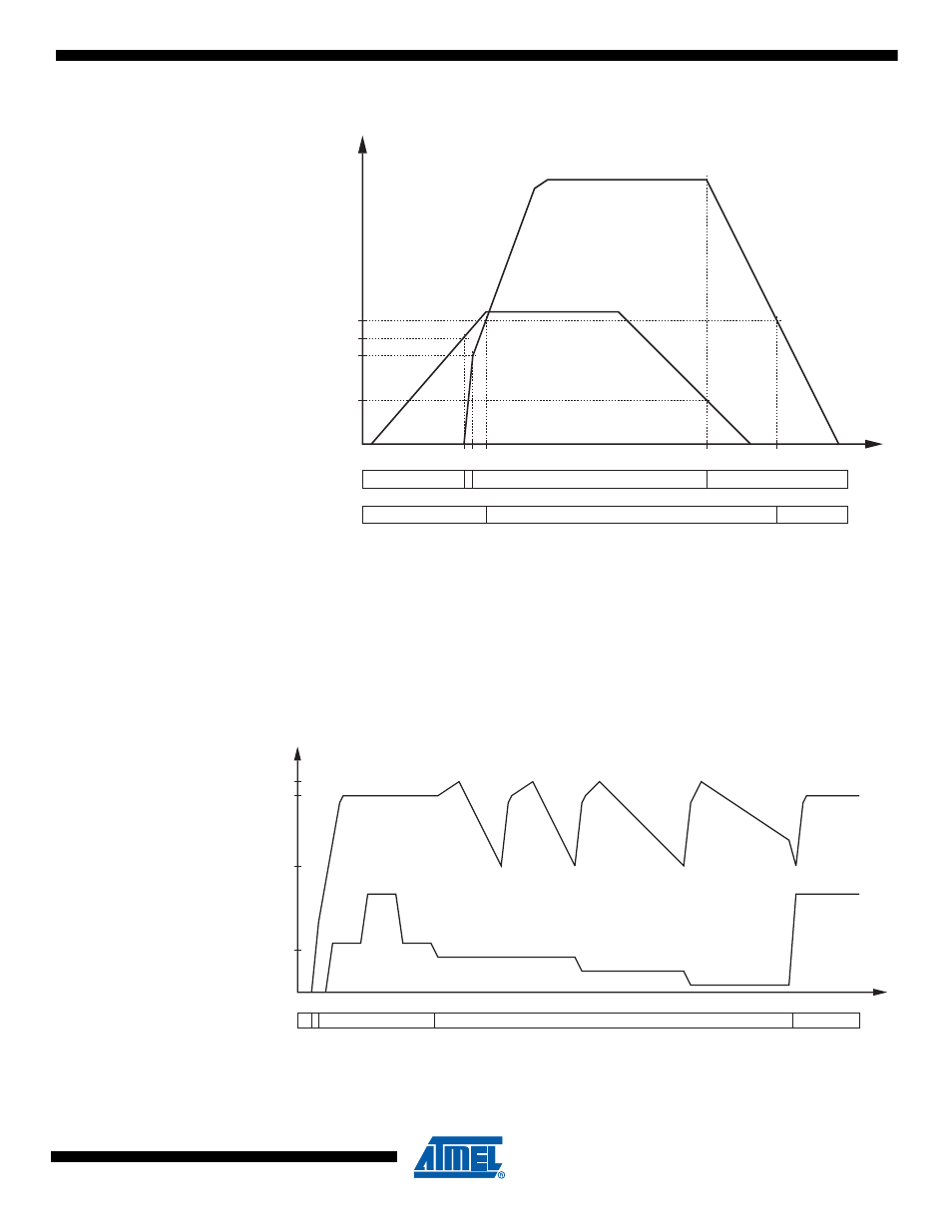
Figure 8-4.
Input and Output Voltages of Boost Converter.
When input voltage V
BAT
falls below V
STOP
the converter enters Stop Mode and output voltage
V
CC
begins to fall. When converter output voltage, i.e. the supply voltage of the microcontroller,
falls below V
POT
the MCU will go into reset.
illustrates how the boost converter output changes with load current. As converter
output voltage rises above the power-on threshold the microcontroller is brought on-line and cur-
rent consumption steps up to a level sufficiently high for the converter to remain in Active
Regulated Mode of operation.
Figure 8-5.
Output Voltage vs. Load Current of Boost Converter.
Note:
The figure is not to scale. Typically, the switching time (rising voltage) is measured in hundreds of
microseconds and idle time (falling voltage) is measured in seconds.
V
CC
t
V
POT
V
START
V
BOOST
V
STOP
V
BAT
STOP
STOP
ACTIVE
RESET
ACTIVE
RESET
CONVERTER:
MCU CORE:
V
CC
t
I
LOAD
V/A
V
CCMIN
V
CCMAX
LOW CURRENT MODE
ACTIVE, REGULATED
MODE:
V
CCNOM
I
MS
REGULATED