Power management and sleep modes, 1 sleep modes, 1 idle mode – Rainbow Electronics ATtiny43U User Manual
Page 31: Power management and sleep
31
8048B–AVR–03/09
7.
Power Management and Sleep Modes
Sleep modes enable the application to shut down unused modules in the MCU, thereby saving
power. The AVR provides various sleep modes allowing the user to tailor the power consump-
tion to the application’s requirements.
When enabled, the Brown-out Detector (BOD) actively monitors the power supply voltage during
the sleep periods. To further save power, it is possible to disable the BOD in some sleep modes.
See
“Software BOD Disable” on page 32
for more details.
7.1
Sleep Modes
presents the different clock systems in ATtiny43U, and their distribution.
The figure is helpful in selecting an appropriate sleep mode.
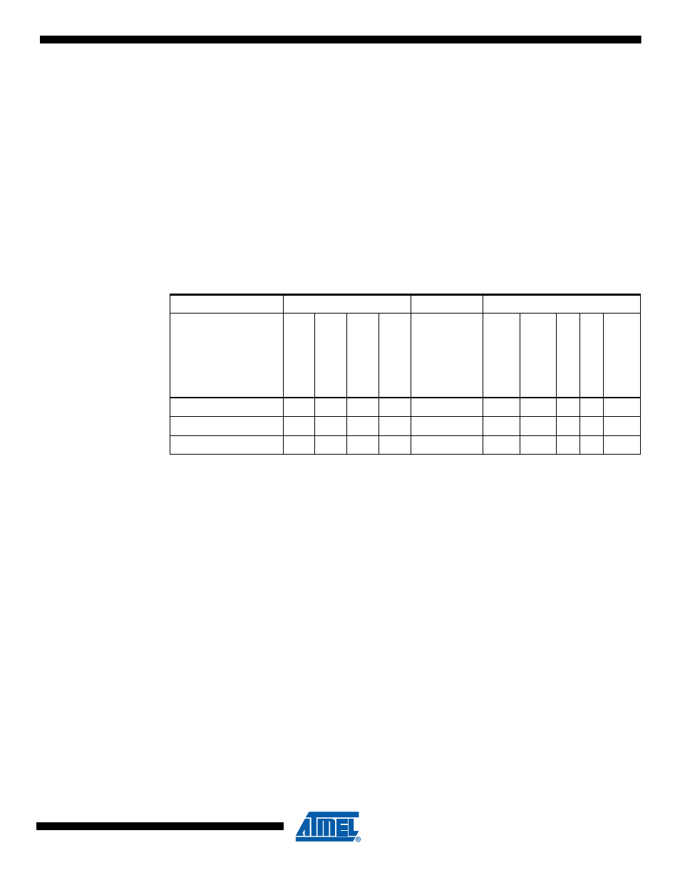
below shows the different
sleep modes and their wake-up sources.
Note:
1. For INT0, only level interrupt.
To enter any of the sleep modes, the SE bit in MCUCR must be written to logic one and a
SLEEP instruction must be executed. The SM1:0 bits in the MCUCR Register select which sleep
mode (Idle, ADC Noise Reduction or Power-down) will be activated by the SLEEP instruction.
See
for a summary.
If an enabled interrupt occurs while the MCU is in a sleep mode, the MCU wakes up. The MCU
is then halted for four cycles in addition to the start-up time, executes the interrupt routine, and
resumes execution from the instruction following SLEEP. The contents of the Register File and
SRAM are unaltered when the device wakes up from sleep. If a reset occurs during sleep mode,
the MCU wakes up and executes from the Reset Vector.
Note that if a level triggered interrupt is used for wake-up the changed level must be held for
some time to wake up the MCU (and for the MCU to enter the interrupt service routine). See
“External Interrupts” on page 58
for details.
7.1.1
Idle Mode
When the SM1:0 bits are written to 00, the SLEEP instruction makes the MCU enter Idle mode,
stopping the CPU but allowing Analog Comparator, ADC, Timer/Counter, Watchdog, and the
interrupt system to continue operating. This sleep mode basically halts clk
CPU
and clk
FLASH
, while
allowing the other clocks to run.
Table 7-1.
Active Clock Domains and Wake-up Sources in the Different Sleep Modes
Active Clock Domains
Oscillators
Wake-up Sources
Sleep Mode
clk
CPU
clk
FL
AS
H
clk
IO
clk
ADC
Mai
n
Cloc
k
So
urce En
ab
le
d
INT0 and
Pi
n C
hang
e
SPM/EE
P
R
O
M
R
eady
ADC
Other I/O
W
a
tchdog
Interr
upt
Idle
X
X
X
X
X
X
X
X
ADC Noise Reduction
X
X
X
X
X
X
Power-down
X
X