Rainbow Electronics ATtiny43U User Manual
Page 105
105
8048B–AVR–03/09
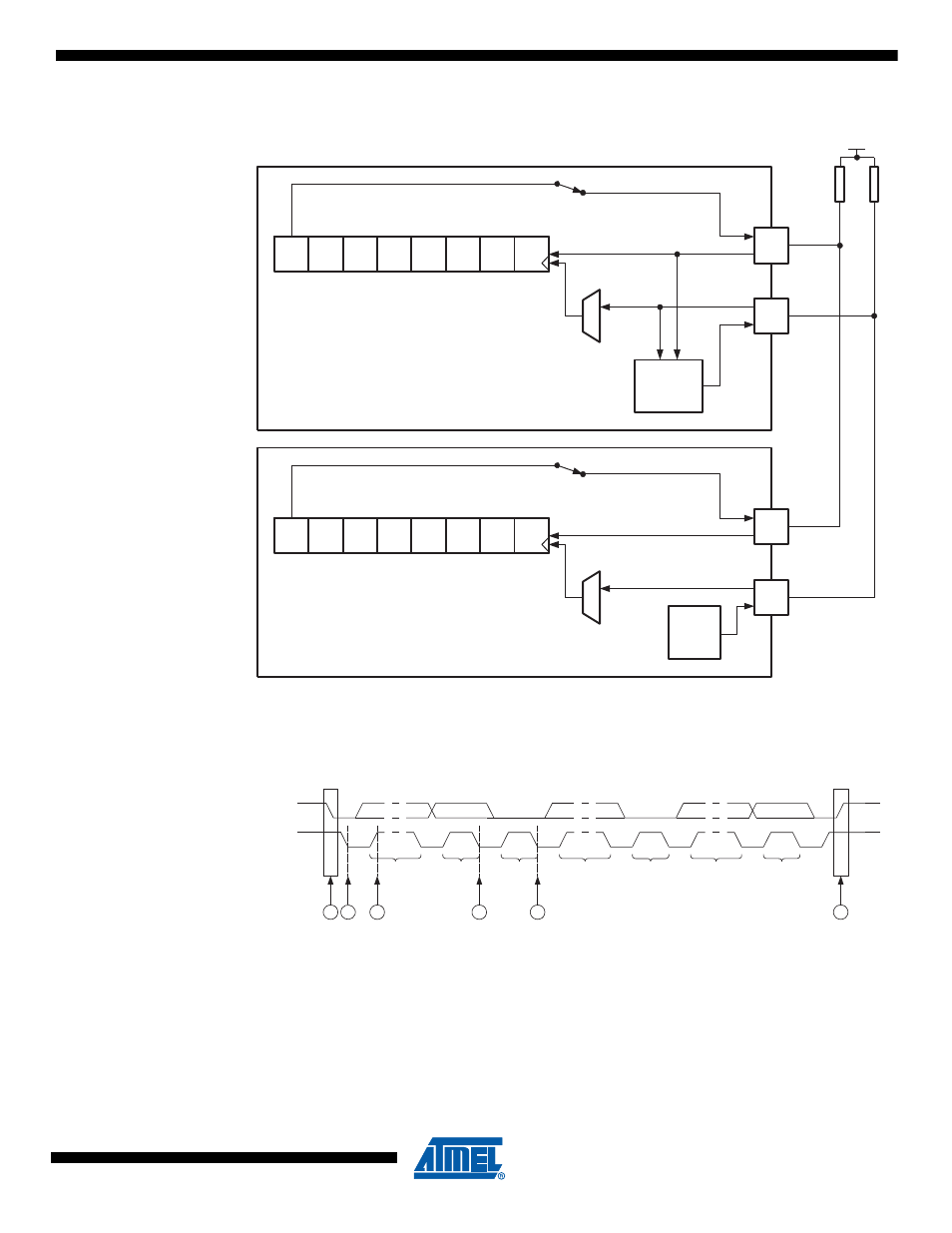
Figure 14-4. Two-wire Mode Operation, Simplified Diagram
The data direction is not given by the physical layer. A protocol, like the one used by the TWI-
bus, must be implemented to control the data flow.
Figure 14-5. Two-wire Mode, Typical Timing Diagram
Referring to the timing diagram (
), a bus transfer involves the following steps:
1.
The start condition is generated by the master by forcing the SDA low line while keep-
ing the SCL line high (A). SDA can be forced low either by writing a zero to bit 7 of the
USI Data Register, or by setting the corresponding bit in the PORTA register to zero.
Note that the Data Direction Register bit must be set to one for the output to be
enabled. The start detector logic of the slave device (see
)
MASTER
SLAVE
Bit7
Bit6
Bit5
Bit4
Bit3
Bit2
Bit1
Bit0
SDA
SCL
Bit7
Bit6
Bit5
Bit4
Bit3
Bit2
Bit1
Bit0
Two-wire Clock
Control Unit
HOLD
SCL
PORTxn
SDA
SCL
VCC
P
S
ADDRESS
1 - 7
8
9
R/W
ACK
ACK
1 - 8
9
DATA
ACK
1 - 8
9
DATA
SDA
SCL
A
B
D
E
C
F