Conversion. see, Figure 16-5 – Rainbow Electronics ATtiny43U User Manual
Page 119
119
8048B–AVR–03/09
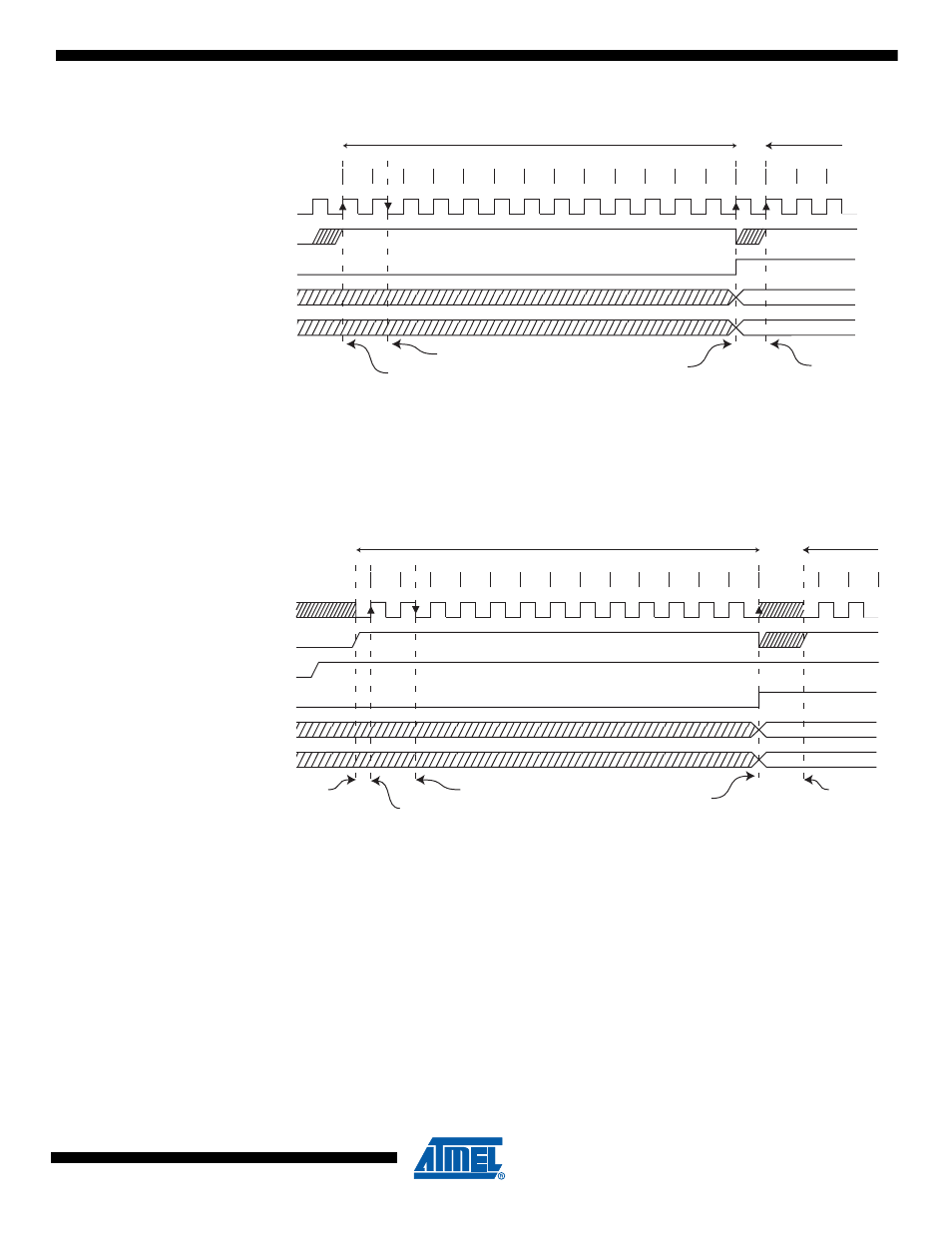
Figure 16-5. ADC Timing Diagram, Single Conversion
When Auto Triggering is used, the prescaler is reset when the trigger event occurs, as shown in
below. This assures a fixed delay from the trigger event to the start of conversion. In
this mode, the sample-and-hold takes place two ADC clock cycles after the rising edge on the
trigger source signal. Three additional CPU clock cycles are used for synchronization logic.
Figure 16-6. ADC Timing Diagram, Auto Triggered Conversion
In Free Running mode, a new conversion will be started immediately after the conversion com-
pletes, while ADSC remains high. See
1
2
3
4
5
6
7
8
9
10
11
12
13
Sign and MSB of Result
LSB of Result
ADC Clock
ADSC
ADIF
ADCH
ADCL
Cycle Number
1
2
One Conversion
Next Conversion
3
Sample & Hold
MUX and REFS
Update
Conversion
Complete
MUX and REFS
Update
1
2
3
4
5
6
7
8
9
10
11
12
13
Sign and MSB of Result
LSB of Result
ADC Clock
Trigger
Source
ADIF
ADCH
ADCL
Cycle Number
1
2
One Conversion
Next Conversion
Conversion
Complete
Prescaler
Reset
ADATE
Prescaler
Reset
Sample &
Hold
MUX and REFS
Update