2 active low current mode, 3 full duty cycle, Figure 8-6 – Rainbow Electronics ATtiny43U User Manual
Page 41
41
8048B–AVR–03/09
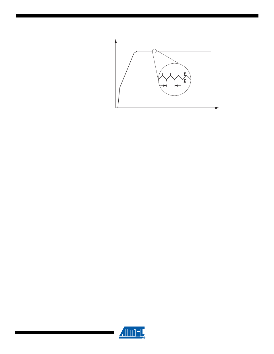
Figure 8-6.
Typical Output Voltage of Boost Converter in Active Regulated Mode.
8.3.2
Active Low Current Mode
The boost converter enters Active Low Current Mode from Active Regulated Mode when output
voltage reaches its maximum and duty cycle is at its minimum. In practice, this means that the
load current drops below a threshold. The threshold varies with converter input voltage and tem-
perature but a typical plot is shown in
From
can be seen that at low input voltages (V
BAT
typically below 1.0V)
and high load currents (I
LOAD
typically above 0.6mA) the boost converter will never enter Low
Current Mode. Using Full Duty Cycle mode the boost converter can be forced to enter Active
Low Current Mode at input voltages lower than those shown in
. See
In Low Current Mode the boost converter stops switching and reduces current consumption to a
minimum, while still remaining active. Provided there are no external loads active the boost con-
verter enters Low Current Mode automatically when the microcontroller goes into Power Down
Mode (see
).
In this mode of operation the converter periodically reaches its duty cycle low limit. When this
happens the converter stops switching and the output voltage starts dropping. The converter
starts switching again when the output voltage has decreased to the low limit of Active Low Cur-
rent Mode. This results in a periodical pattern as illustrated in
.
If the output voltage, V
CC
, drops below V
BOOST
(due to an overload or a short circuit) the con-
verter goes back to Start Mode. In addition, the firmware can instruct the converter to leave this
mode and enter Stop Mode. See
“Software Control of Boost Converter” on page 42
8.3.3
Full Duty Cycle
By default, the boost converter keeps V
CC
within limits by controlling the duty cycle of the switch-
ing waveform. It is possible to bypass the duty cycle regulation and lock the duty cycle at its
maximum, resulting in a V
CC
voltage that quickly ramps up to the maximum limit and then starts
dropping when the boost converter enters Low Current Mode. See
, below.
V
CC
ST
AR
T MODE
ACTIVE REGULATED MODE
t
f
SW
V
RPP