5 output capacitors, 6 summary, Boost converter compo – Rainbow Electronics ATtiny43U User Manual
Page 45
45
8048B–AVR–03/09
Too high resistor values may lead to Start Mode failures. See
“Boost Converter Component Val-
for component recommendations and limits.
Capacitor C
2
should be located close to the device.
8.6.5
Output Capacitors
An output capacitor, C
3
, is required to keep the output voltage stable at times when energy is
transferred to the inductor. It is recommended to use a capacitor with high capacitance and low
Equivalent Series Resistance, ESR. A large capacitance helps to reduce the voltage ripple at
the output and a low ESR reduces voltage ripple and helps to keep the temperature of the
capacitor within limits.
The recommended capacitance at a given, steady-state load is calculated as follows:
... where T
S
is the switching frequency of the boost converter, V
PP
is the allowed voltage ripple
and D is the duty cycle, calculated as shown in
The recommended ESR is calculated as follows:
A secondary output capacitor, C
4
, is recommended and should be placed close to the device.
8.6.6
Summary
The table below summarises recommended component values for a typical application.
Note:
1. With these values the LPF provides a 32dB attenuation at the switching frequency of the boost
converter while permitting a supply voltage ripple of about ±200mV
2. Application specific limits may be tighter
C
OUT
I
LOAD
T
S
D
Ч
Ч
V
PP
--------------------------------------
=
ESR
V
PP
I
PEAK
---------------
≤
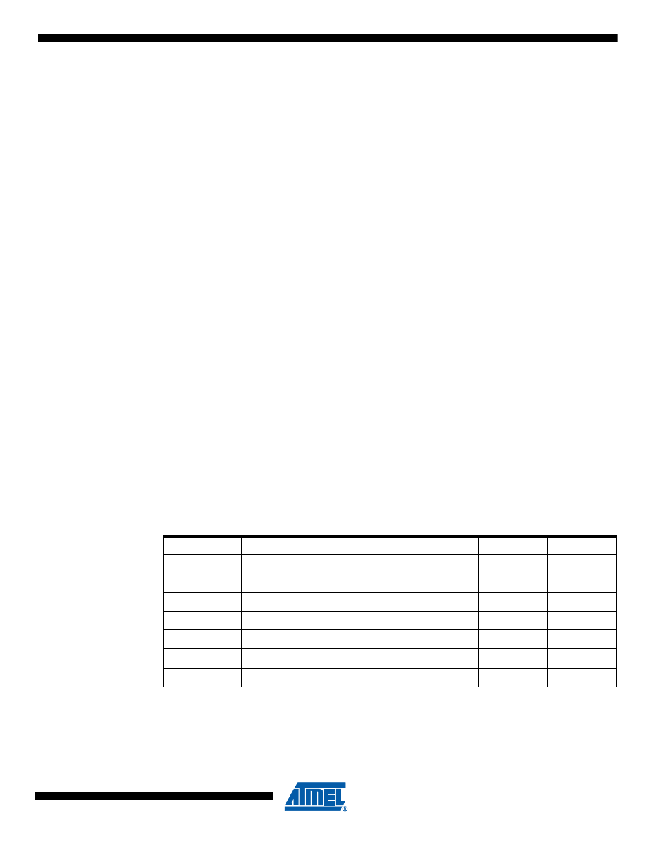
Table 8-1.
Boost Converter Component Values
Component
Recommended Value
Max
C
1
C = 4.7µF
1µF
C
2
C = 100nF
C
3
C = 22µF, ESR < 100m
Ω
10µF
C
4
C = 100nF
100nF
100nF
D
1
I
R
= 1µA @ 25
°
C, V
F
= 0.5V @ 1A
L
1
L = 15µH ±20%, I
MAX
= 700mA, R < 150m
Ω
15µH
15µH
R
1
R = 680
Ω
1k
Ω