2 modes of operation – Rainbow Electronics ATtiny43U User Manual
Page 37
37
8048B–AVR–03/09
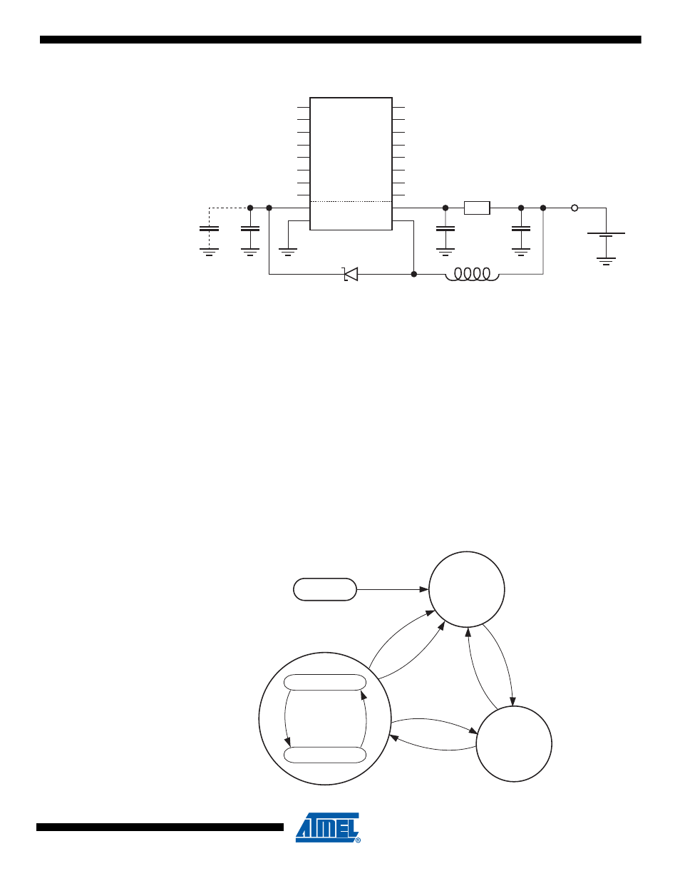
Figure 8-2.
Typical Connection of Boost Converter.
When the boost converter is not connected the microcontroller can be powered directly from an
external source and is then subject to the standard supply voltage limits defined in
It is recommended to disable the Brown-Out Detection (BOD) circuit when using the integrated
boost converter. This is because supply voltage of the microcontroller can drop to lowest BOD
levels during regular operation. See
“Brown-out Detection” on page 50
8.2
Modes of Operation
The boost converter has three main modes of operation; Stop, Start, and Active. Operation
begins from Stop Mode and is transferred to Start Mode when input voltage, V
BAT
, is sufficiently
high for stable operation. When the converter has managed to raise the output voltage, V
CC
, to a
sustainable level control is then transferred to the main mode of operation, Active Mode.
The modes of operation are illustrated in
, below.
Figure 8-3.
Operating Modes of Boost Converter.
PB0
PB1
PB2
PB3
PB4
PB5
PB6
PB7
VCC
GND
PA7
PA6
PA5
PA4
PA3
PA2
PA1
PA0
VBAT
LSW
C
4
C
3
C
2
C
1
R
1
L
1
D
1
VIN
START
MODE
STOP
MODE
V
BA
T
<
V
ST
OP
FIR
MW
AR
E
V
BA
T
>
V
S
TA
R
T
V
BA
T
<
V
ST
OP
V
CC
< V
BOOST
V
CC
> V
BOOST
ENTRY
REGULATED
LOW CURRENT
f(
I
LO
A
D
)
ACTIVE
MODE
f(I
LO
A
D
)