System control and reset, 1 resetting the avr, System control and – Rainbow Electronics ATtiny43U User Manual
Page 48: Attiny43u
48
8048B–AVR–03/09
ATtiny43U
9.
System Control and Reset
9.1
Resetting the AVR
During reset, all I/O Registers are set to their initial values, and the program starts execution
from the Reset Vector. The instruction placed at the Reset Vector must be a RJMP – Relative
Jump – instruction to the reset handling routine. If the program never enables an interrupt
source, the Interrupt Vectors are not used, and regular program code can be placed at these
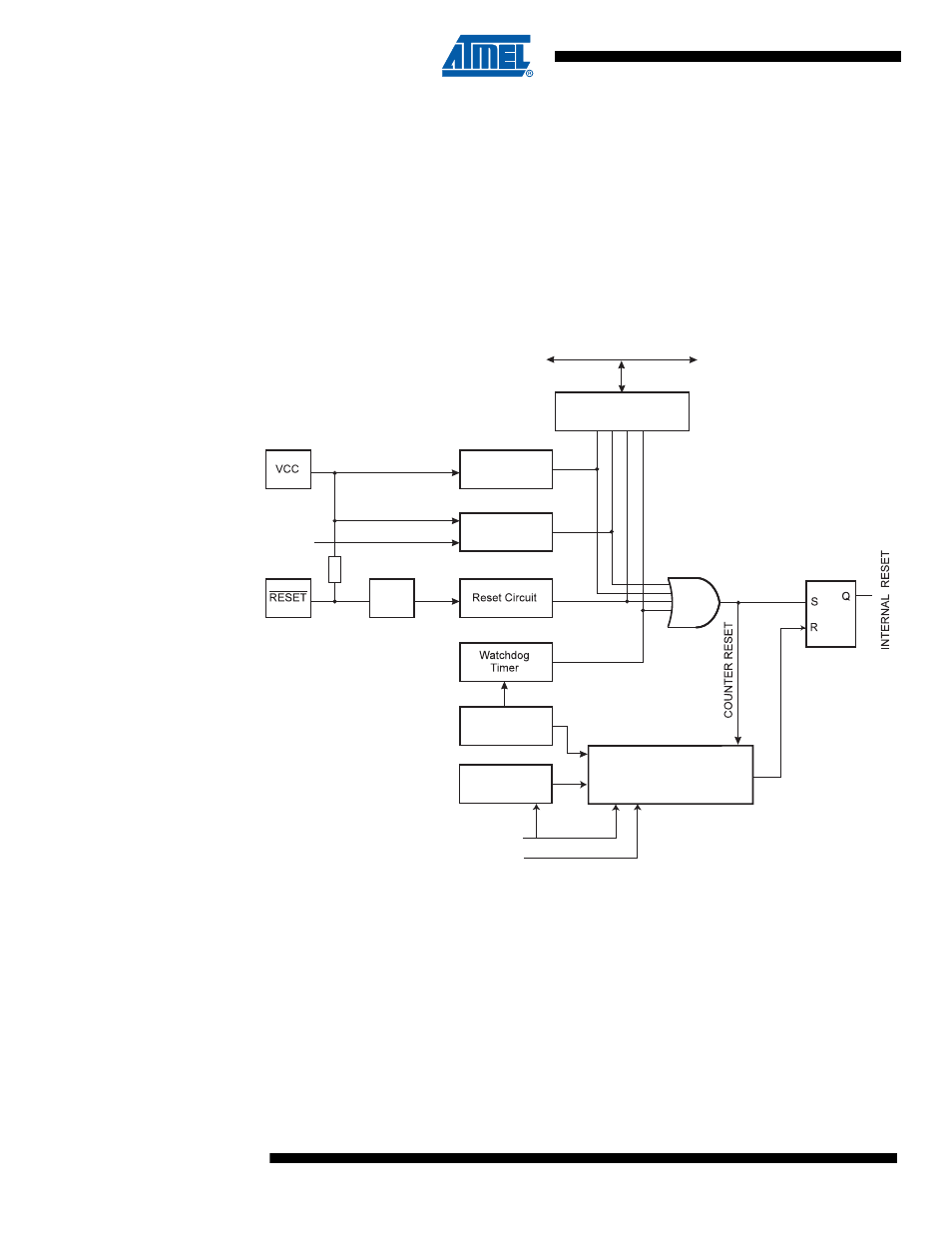
locations. The circuit diagram in
shows the reset logic.
defines the electrical parameters of the reset circuitry.
Figure 9-1.
Reset Logic
The I/O ports of the AVR are immediately reset to their initial state when a reset source goes
active. This does not require any clock source to be running.
After all reset sources have gone inactive, a delay counter is invoked, stretching the internal
reset. This allows the power to reach a stable level before normal operation starts. The time-out
period of the delay counter is defined by the user through the SUT and CKSEL Fuses. The dif-
ferent selections for the delay period are presented in
MCU Status
Register (MCUSR)
Brown-out
Reset Circuit
BODLEVEL [2..0]
Delay Counters
CKSEL[1:0]
CK
TIMEOUT
WDRF
BORF
EXTRF
PORF
DATA BUS
Clock
Generator
SPIKE
FILTER
Pull-up Resistor
Watchdog
Oscillator
SUT[1:0]
Power-on Reset
Circuit