3 adcl and adch – adc data register, 1 adlar = 0, 2 adlar = 1 – Rainbow Electronics ATtiny43U User Manual
Page 128: Attiny43u
128
8048B–AVR–03/09
ATtiny43U
• Bit 4 – ADIF: ADC Interrupt Flag
This bit is set when an ADC conversion completes and the data registers are updated. The ADC
Conversion Complete Interrupt is executed if the ADIE bit and the I-bit in SREG are set. ADIF is
cleared by hardware when executing the corresponding interrupt handling vector. Alternatively,
ADIF is cleared by writing a logical one to the flag. Beware that if doing a Read-Modify-Write on
ADCSRA, a pending interrupt can be disabled. This also applies if the SBI instruction is used.
• Bit 3 – ADIE: ADC Interrupt Enable
When this bit is written to one and the I-bit in SREG is set, the ADC Conversion Complete Inter-
rupt is activated.
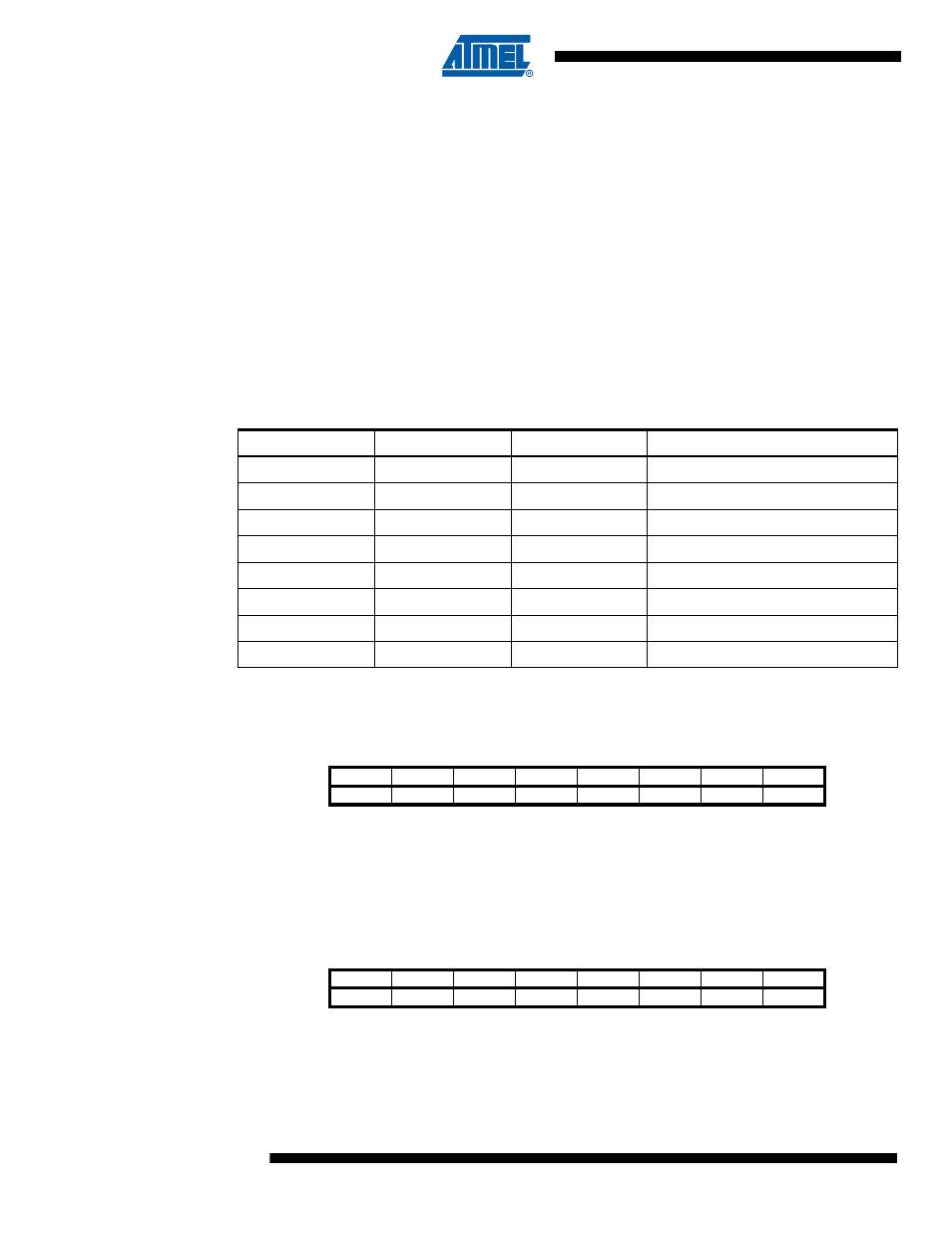
• Bits 2:0 – ADPS2:0: ADC Prescaler Select Bits
These bits determine the division factor between the system clock frequency and the input clock
to the ADC.
16.13.3
ADCL and ADCH – ADC Data Register
16.13.3.1
ADLAR = 0
16.13.3.2
ADLAR = 1
Table 16-5.
ADC Prescaler Selections
ADPS2
ADPS1
ADPS0
Division Factor
0
0
0
2
0
0
1
2
0
1
0
4
0
1
1
8
1
0
0
16
1
0
1
32
1
1
0
64
1
1
1
128
Bit
15
14
13
12
11
10
9
8
–
–
–
–
–
–
ADC9
ADC8
ADCH
ADC7
ADC6
ADC5
ADC4
ADC3
ADC2
ADC1
ADC0
ADCL
7
6
5
4
3
2
1
0
Read/Write
R
R
R
R
R
R
R
R
R
R
R
R
R
R
R
R
Initial Value
0
0
0
0
0
0
0
0
0
0
0
0
0
0
0
0
Bit
15
14
13
12
11
10
9
8
ADC9
ADC8
ADC7
ADC6
ADC5
ADC4
ADC3
ADC2
ADCH
ADC1
ADC0
–
–
–
–
–
–
ADCL
7
6
5
4
3
2
1
0
Read/Write
R
R
R
R
R
R
R
R
R
R
R
R
R
R
R
R
Initial Value
0
0
0
0
0
0
0
0
0
0
0
0
0
0
0
0