6 watchdog reset, 7 internal voltage reference, 8 watchdog timer – Rainbow Electronics ATtiny43U User Manual
Page 51: Internal voltage
51
8048B–AVR–03/09
It is recommended to disable the BOD when using the integrated boost converter. See
Supply and On-Chip Boost Converter” on page 36
9.6
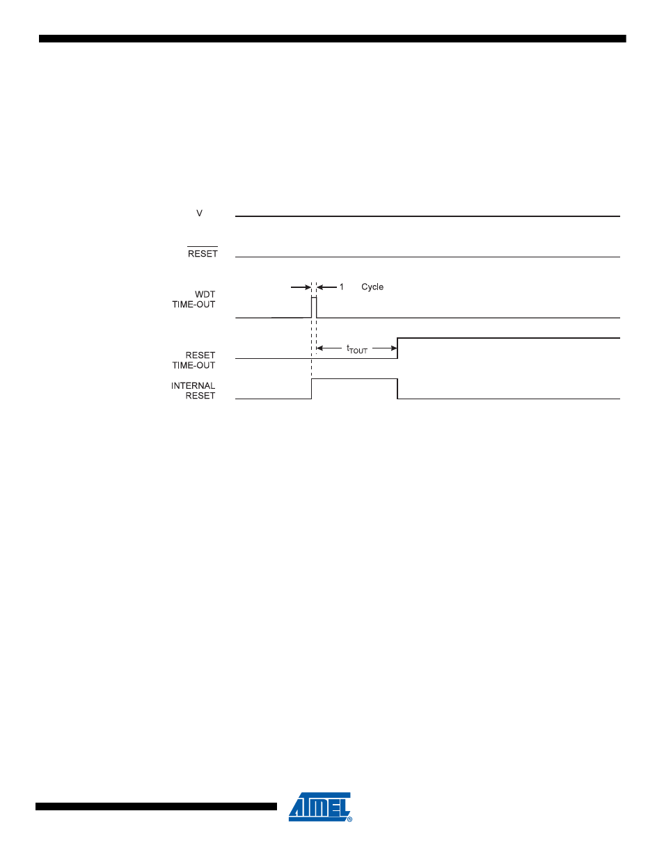
Watchdog Reset
When the Watchdog times out, it will generate a short reset pulse of one CK cycle duration. On
the falling edge of this pulse, the delay timer starts counting the Time-out period t
TOUT
. See
for details on operation of the Watchdog Timer.
Figure 9-6.
Watchdog Reset During Operation
9.7
Internal Voltage Reference
ATtiny43U features an internal bandgap reference. This reference is used for Brown-out Detec-
tion, and it can be used as an input to the Analog Comparator or the ADC.
9.7.1
Voltage Reference Enable Signals and Start-up Time
The voltage reference has a start-up time that may influence the way it should be used. The
start-up time is given in
. To save power, the reference is not always
turned on. The reference is on during the following situations:
1.
When the BOD is enabled (by programming the BODLEVEL [2..0] Fuse).
2.
When the bandgap reference is connected to the Analog Comparator (by setting the
ACBG bit in ACSR).
3.
When the ADC is enabled.
Thus, when the BOD is not enabled, after setting the ACBG bit or enabling the ADC, the user
must always allow the reference to start up before the output from the Analog Comparator or
ADC is used. To reduce power consumption in Power-down mode, the user can avoid the three
conditions above to ensure that the reference is turned off before entering Power-down mode.
9.8
Watchdog Timer
The Watchdog Timer is clocked from an On-chip Oscillator which runs at 128 kHz. By controlling
the Watchdog Timer prescaler, the Watchdog Reset interval can be adjusted as shown in
. The WDR – Watchdog Reset – instruction resets the Watchdog Timer. The
Watchdog Timer is also reset when it is disabled and when a Chip Reset occurs. Ten different
CK
CC