Ac electrical characteristics – Rainbow Electronics MAX14821 User Manual
Page 6
����������������������������������������������������������������� Maxim Integrated Products 6
MAX14821
IO-Link Device Transceiver
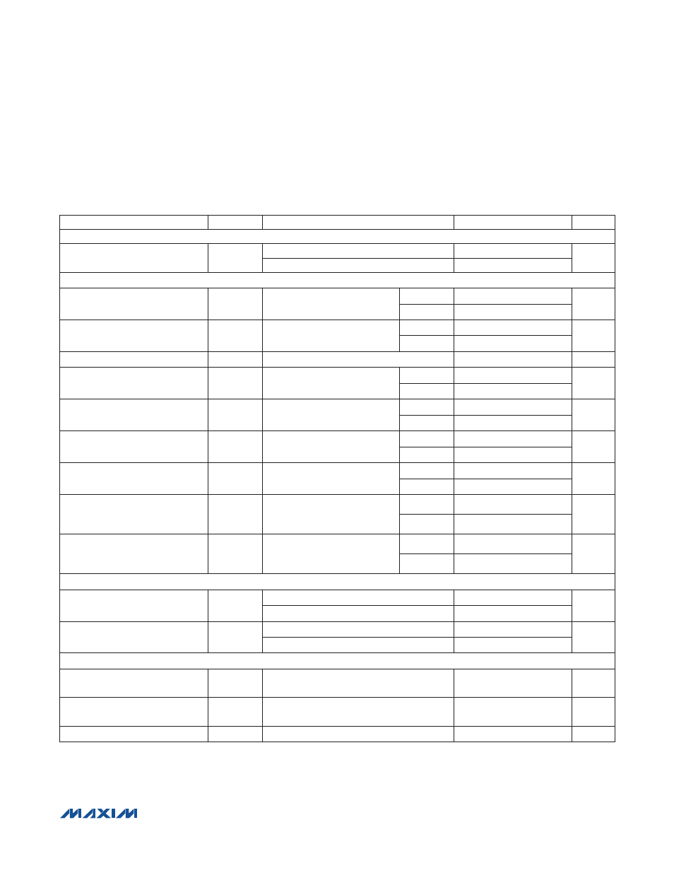
AC ELECTRICAL CHARACTERISTICS
(V
CC
= 18V to 36V, V
L
= 2.3V to 5.5V, V
GND
= 0V; all logic inputs at V
L
or GND; T
A
= -40NC to +85NC, unless otherwise noted. Typical
values are at V
CC
= 24V, V
L
= 3.3V, and T
A
= +25NC, unless otherwise noted.) (Note 2)
PARAMETER
SYMBOL
CONDITIONS
MIN
TYP
MAX
UNITS
C/Q, DO, DI INTERFACES
Data Rate
DR
HiSlew = 1
4.8
230.4
kbps
HiSlew = 0
4.8
38.4
DRIVER (C/Q, DO)
Driver Low-to-High Propagation
Delay
t
PDLH
Push-pull or high-side (PNP)
configuration, Figure 1
HiSlew = 1
0.5
2
F
s
HiSlew = 0
1.6
5
Driver High-to-Low Propagation
Delay
t
PDHL
Push-pull or low-side (NPN)
configuration, Figure 1
HiSlew = 1
0.5
2
F
s
HiSlew = 0
1.6
5
Driver Skew
t
SKEW
|t
PDLH
- t
PDHL
|
0.1
2
F
s
Driver Rise Time
t
RISE
Push-pull or high-side (PNP)
configuration, Figure 1
HiSlew = 1
0.4
1.7
F
s
HiSlew = 0
1.5
4
Driver Fall Time
t
FALL
Push-pull or low-side (NPN)
configuration, Figure 1
HiSlew = 1
0.4
1.7
F
s
HiSlew = 0
1.4
4
Driver Enable Time High
t
ENH
Push-pull or high-side (PNP)
configuration, Figure 3
HiSlew = 1
0.3
1
F
s
HiSlew = 0
0.8
7
Driver Enable Time Low
t
ENL
Push-pull or low-side (NPN)
configuration, Figure 2
HiSlew = 1
0.3
1
F
s
HiSlew = 0
0.9
7
Driver Disable Time High
t
DISH
Push-pull or high-side (PNP)
configuration, Figure 2
(Note 4)
HiSlew = 1
1.6
3
F
s
HiSlew = 0
1.6
3
Driver Disable Time Low
t
DISL
Push-pull or low-side (NPN)
configuration, Figure 3
(Note 4)
HiSlew = 1
0.1
3
F
s
HiSlew = 0
0.1
3
RECEIVER (C/Q, DI) (Figure 4)
Receiver Low-to-High
Propagation Delay
t
PRLH
RxFilter = 1
0.2
2
F
s
RxFilter = 0
0.4
2
Receiver High-to-Low
Propagation Delay
t
PRHL
RxFilter = 1
0.3
2
F
s
RxFilter = 0
0.5
2
WAKE-UP DETECTION (Figure 5)
Wake-Up Input Minimum Pulse
Width
t
WUMIN
30
40
50
F
s
Wake-Up Input Maximum Pulse
Width
t
WUMAX
120
140
160
F
s
WU Output Low Time
t
WUL
Valid wake-up condition on C/Q
120
190
260
F
s