Mode register [r1, r0] = [1,1 – Rainbow Electronics MAX14821 User Manual
Page 25
���������������������������������������������������������������� Maxim Integrated Products 25
MAX14821
IO-Link Device Transceiver
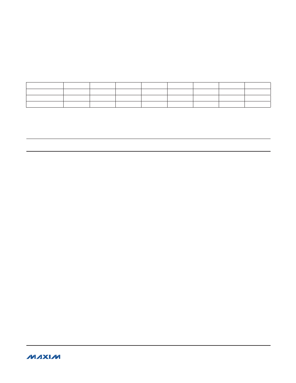
Mode Register [R1, R0] = [1,1]
Bit
D7
D6
D5
D4
D3
D2
D1
D0
Bit Name
RST
WuIntEn
DoFault
C/QFault
UV24
OTemp
UV33En
LDO33Dis
Read/Write
R/W
R/W
R
R
R
R
R
R/W
POR State
0
0
0
0
0
0
0
0
Use the Mode register to reset the MAX14821 and manage the 3.3V LDO. The Mode register has bits that repre-
sent the current status of fault conditions. When writing to the Mode register, the contents of the fault indication bits
(bits 2 to 5) do not change.
BIT
NAME
DESCRIPTION
D7
RST
Register Reset. Set RST to 1 to reset all registers to their default power-up state. Then
set RST to 0 for normal operation.
The Status register is cleared and IRQ deasserts (if asserted) when RST = 1. Interrupts
are not generated while RST = 1.
D6
WuIntEn
Wake-Up Interrupt Enable. Set WuIntEn to 1 to enable wake-up interrupt generation.
When WuIntEn is set, the WuInt bit in the Status register is set and IRQ asserts when
a valid wake-up condition is detected. The C/Q driver must be enabled for wake-up
detection. The state of WuIntEn does not affect the WU output. See the Wake-Up
Detection section for more information.
D5
DoFault
DO Fault Status. The DoFault bit is set when a short circuit or voltage fault occurs at
the DO driver output (see the DO Fault Detection section for more information). The
DoFault and DoFaultInt bits are both set when a fault occurs on DO. DoFault is cleared
when the fault is removed.
D4
C/QFault
C/Q Fault Status. The C/QFault bit is set when a short circuit or voltage fault occurs at
the C/Q driver output (see the C/Q Fault Detection section for more information). The
C/QFault and C/QFaultInt bits are both set when a fault occurs on C/Q. C/QFault is
cleared when the fault is removed.
D3
UV24
V
CC
Undervoltage Condition. Both the UV24 and the UV24Int bits are set when V
CC
falls below V
CCUVLO
. UV24 is cleared when V
CC
rises above the V
CC
threshold. V
5
must be present for V
CC
undervoltage monitoring.
D2
OTemp
Temperature Warning. The OTemp bit is set when a high-temperature condition
occurs on the device. Both the OTempInt interrupt in the Status register and the OTemp
bit are set when the junction temperature of the die rises to above +115NC (typ). The
OTemp bit is cleared when the junction temperature falls below +95NC (typ).
D1
UV33En
LDO33 UV Enable. Set the UV33En bit to 1 to assert the UV output when LDO33 volt-
age falls below the 2.4V (typ) undervoltage-lockout threshold. The UV33En bit does
not affect the UV33Int bit in the Status register; IRQ asserts when V
LDO33
falls below
V
LDO33UVLO
regardless of the state of UV33En.
D0
LDO33Dis
LDO33 Enable/Disable. Set LDO33Dis to 1 to disable the 3.3V linear regulator (LDO33).