Cqconfig register [r1, r0] = [0,1 – Rainbow Electronics MAX14821 User Manual
Page 21
���������������������������������������������������������������� Maxim Integrated Products 21
MAX14821
IO-Link Device Transceiver
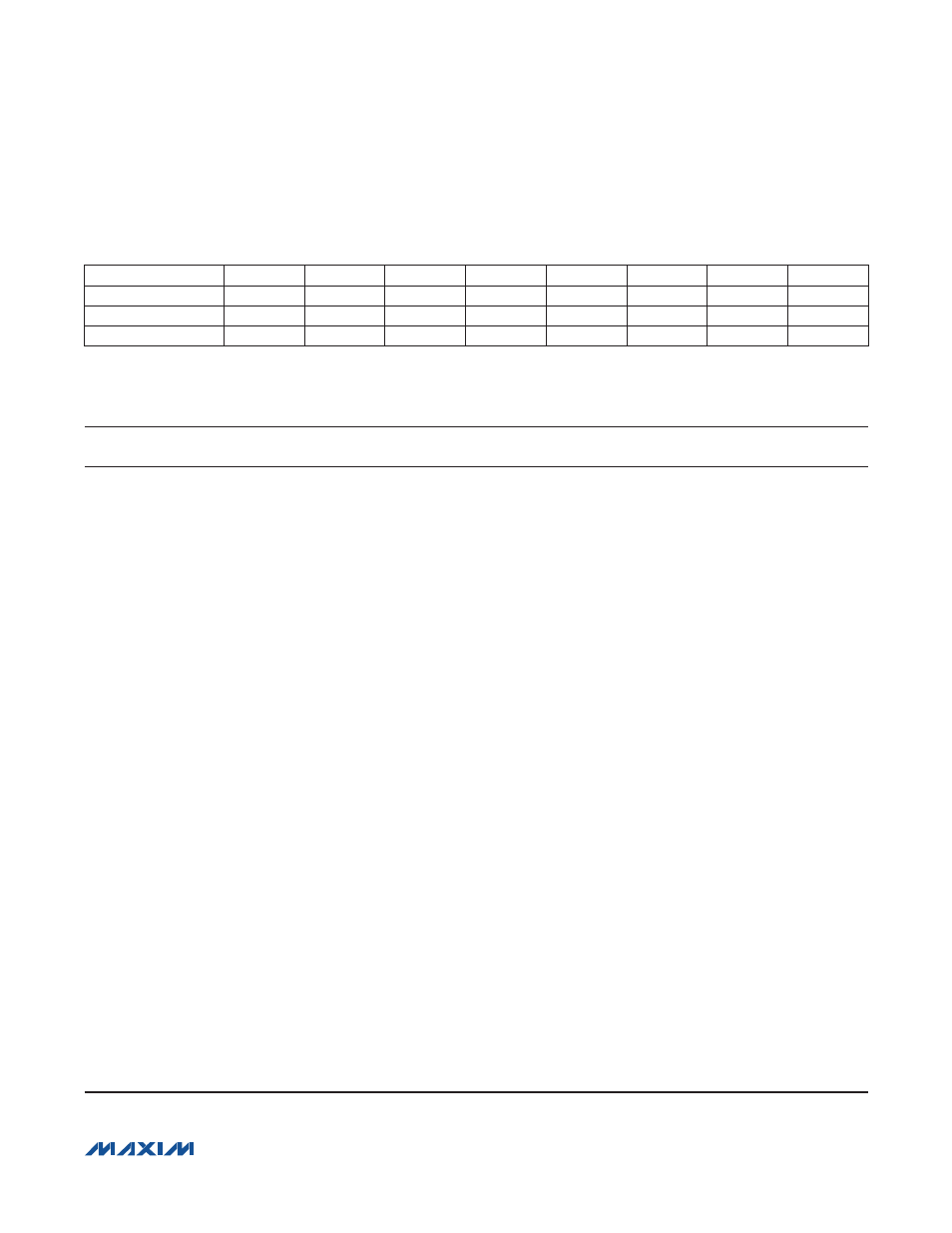
CQConfig Register [R1, R0] = [0,1]
Bit
D7
D6
D5
D4
D3
D2
D1
D0
Bit Name
RxFilter
HiSlew
C/Q_N/P
C/Q_PP
C/QDEn
Q
RxDis
C/QLoad
Read/Write
R/W
R/W
R/W
R/W
R/W
R/W
R/W
R/W
POR State
0
0
0
0
0
0
0
0
Use the CQConfig register to control the C/Q receiver and driver parameters. All bits in the CQConfig register are
read-write and are set to 0 at power-up.
BIT
NAME
DESCRIPTION
D7
RxFilter
C/Q and DI Receiver Filter Control. The C/Q and DI receivers have analog
lowpass filters to reduce high-frequency noise on the receiver inputs. Set the
RxFilter bit to 0 to set the filter corner frequency to 500kHz. Set the RxFilter
bit to 1 to set the filter corner frequency to 1MHz (this setting is used for high-
speed COM3 operation).
Noise filters on C/Q and DI are controlled simultaneously by the RxFilter bit.
D6
HiSlew
Slew-Rate Control. The HiSlew bit increases the slew rate for the C/Q and
DO drivers and is used for high-speed COM3 (230kbps) data rates. Set
HiSlew to 0 for COM1 and COM2 operation.
D5
C/Q_N/P
C/Q Driver NPN/PNP Mode. The C/Q_N/P bit selects between low-side (NPN)
and high-side (PNP) modes when the C/Q driver is configured as an open-
drain output (C/Q_PP = 0). Set C/Q_N/P to 1 to configure the driver for low-side
(NPN) operation. Set C/Q_N/P to 0 for high-side (PNP) operation.
D4
C/Q_PP
C/Q Driver Push-Pull Operation. Set C/Q_PP to 1 to enable push-pull
operation on the C/Q driver. The C/Q output is open-drain when C/Q_PP is 0.
D3
C/QDEn
C/Q Driver Enable/Disable. Set the C/QDEn bit to 1 to enable the C/Q driver.
Set C/QDEn to 0 for hardware (TXEN) control. See Table 4.
D2
Q
C/Q Driver Output Logic. The Q bit can be used to program the C/Q output
driver through software. The C/Q driver must be enabled and TXC = TXQ must
be high to control the C/Q driver through the Q bit (Figure 8). C/Q has the
same logic polarity as the Q bit.
Set the Q bit to 0 to control the C/Q driver with TXC and TXQ.
The C/Q driver output state depends on the C/Q_PP and C/Q_N/P bits as
shown in Table 5. Note that Table 5 assumes that the C/Q driver is enabled
(TXEN = V
L
or C/QDEn = 1).
D1
RxDis
C/Q Receiver Enable/Disable. Set the RxDis bit to 1 to disable the C/Q
receiver. The RX output is high when RxDis is 1.
D0
C/QLoad
C/Q Current Sink Enable. Set the C/QLoad bit to 1 to enable the internal
current sink at C/Q.