Register functionality, Status register [r1, r0] = [0,0, Table 1. register summary – Rainbow Electronics MAX14821 User Manual
Page 19
���������������������������������������������������������������� Maxim Integrated Products 19
MAX14821
IO-Link Device Transceiver
Status Register [R1, R0] = [0,0]
Register Functionality
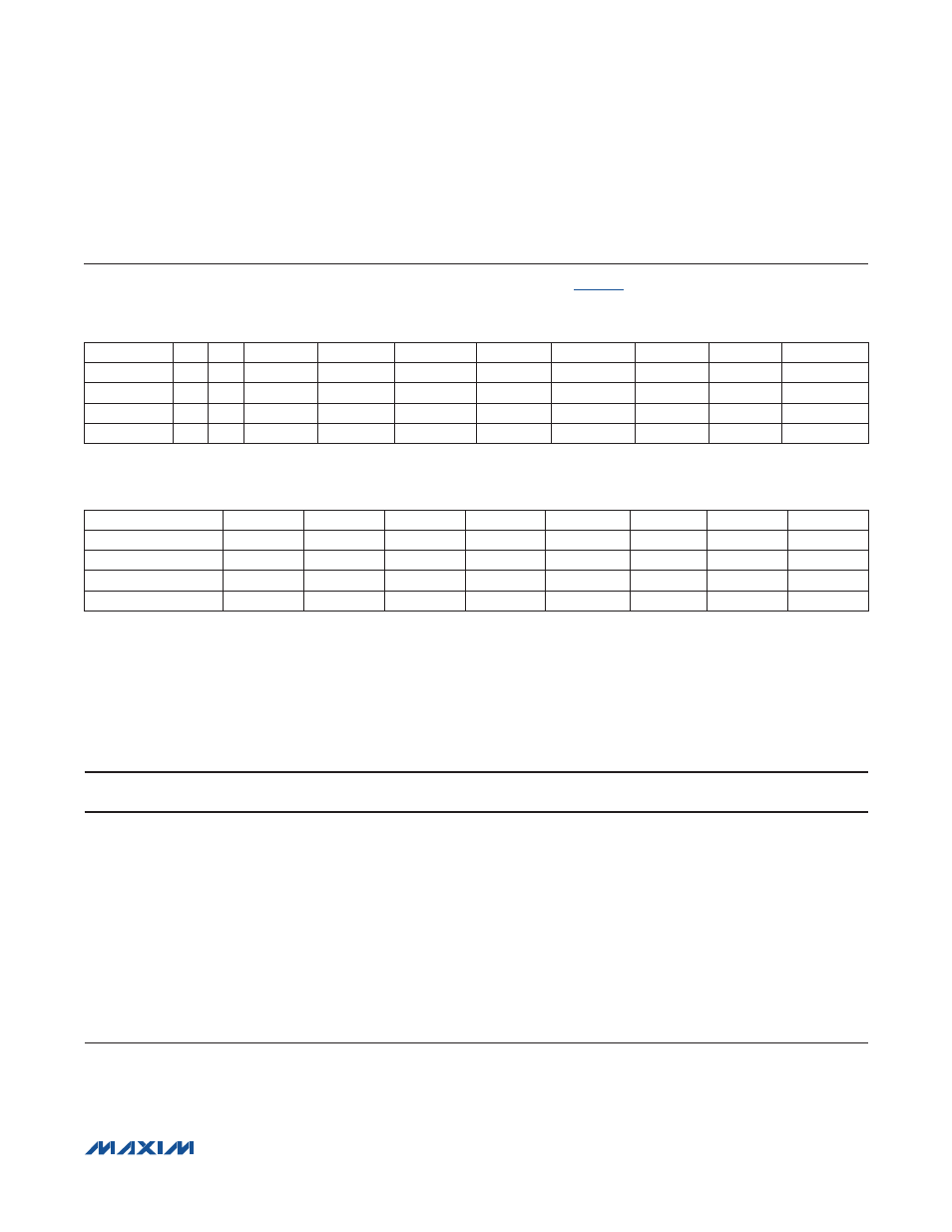
The device has four 8-bit-wide registers for configuration and monitoring (
).
Table 1. Register Summary
R1/R0 = Register address.
REGISTER
R1
R0
D7
D6
D5
D4
D3
D2
D1
D0
Status
0
0
WuInt
DoFaultInt
DiLvl
QLvl
C/QFaultInt
UV33Int
UV24Int
OTempInt
CQConfig
0
1
RxFilter
HiSlew
C/Q_N/P
C/Q_PP
C/QDEn
Q
RxDis
C/QLoad
DIOConfig
1
0
DoInv
DoAv
DoN/P
DoPP
DoEn
DoBit
LiDis
DiLoad
Mode
1
1
RST
WuIntEn
DoFault
C/QFault
UV24
OTemp
UV33En
LDO33Dis
Bit
D7
D6
D5
D4
D3
D2
D1
D0
Bit Name
WuInt
DoFaultInt
DiLvl
QLvl
C/QFaultInt
UV33Int
UV24Int
OTempInt
Read/Write
R
R
R
R
R
R
R
R
POR State
0
0
X
X
0
0
0
0
Reset Upon Read
Yes
Yes
No
No
Yes
Yes
Yes
Yes
X = Unknown. These bits are dependent on the DI logic and C/Q inputs.
The Status register reflects the logic levels of C/Q and DI and shows the source of interrupts that cause an IRQ
hardware interrupt. The IRQ interrupt is asserted when an alarm condition (OTemp, UV33Int, UV24, C/QFault,
DoFault, WuInt) is detected. All bits in the Status register are read-only. The interrupt bits return to the default state
after the Status register is read. If a C/Q or DO fault condition persists, the associated interrupt bits are immediately
set after the Status register is read.
BIT
NAME
DESCRIPTION
D7
Wulnt
Wake-Up Interrupt Request. WuInt is set when an IO-Link wake-up request pulse is
detected on C/Q and the WuIntEn bit in the Mode register is set. IRQ asserts when
WuInt is set to 1. Read the Status register to clear the WuInt bit and deassert IRQ.
D6
DoFaultInt
DO Fault Interrupt. DoFaultInt interrupt bit and DoFault bit (in the Mode register) are
set when a fault condition occurs on the DO driver output. The device registers a fault
condition when a short circuit or voltage fault is detected on DO (see the DO Fault
Detection section for more information). IRQ asserts when DoFaultInt is 1. Read the
Status register to clear the DoFaultInt bit and deassert IRQ.
D5
DiLvl
DI Logic Level. The DiLvl bit mirrors the current logic level at the DI input. It is the
inverse of the LI output and is always active regardless of the state of the LiDis bit (Table
2). DiLvl does not affect IRQ. DiLvl is not changed when the Status register is read.