Do fault detection, Reverse-polarity protection, 5v and 3.3v linear regulators – Rainbow Electronics MAX14821 User Manual
Page 17: Power-up, Undervoltage detection, Wake-up detection, Figure 7. v5 compensation network
���������������������������������������������������������������� Maxim Integrated Products 17
MAX14821
IO-Link Device Transceiver
DO Fault Detection
The device registers a DoFault event when a short circuit
is present at the DO output for longer than 30–440Fs. A
short condition exists when the load current on the DO
driver exceeds the 135mA (typ) DO current limit. When a
short-circuit condition is detected, the DO driver enters
autoretry mode. In autoretry mode the device periodi-
cally checks whether the error is still present. Autoretry
attempts last for 440µs (typ) and occur every 26ms
(typ). When a DoFault error is detected, the DoFault and
DoFaultInt bits are set, IRQ asserts, and the driver is
turned off 440µs (typ) after the start of the DO faults.
Reverse-Polarity Protection
The device is protected against reverse-polarity connec-
tions on V
CC
, C/Q, DO, DI, and GND. Any combination
of these pins can be connected to DC voltages up to
40V (max). A short to 40V results in a current flow of less
than 500FA.
Ensure that the maximum voltage between any of these
pins does not exceed 40V.
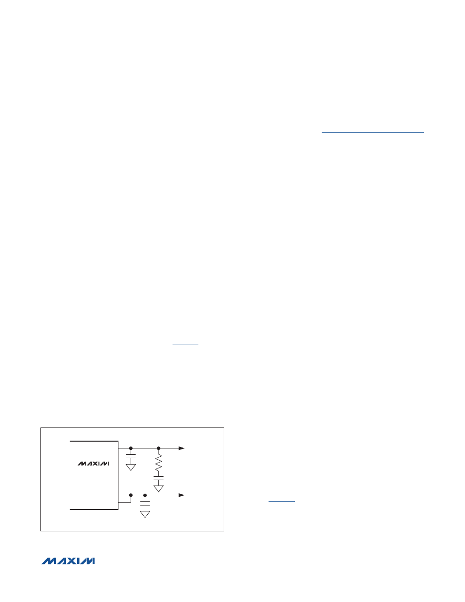
5V and 3.3V Linear Regulators
The device includes two internal current-limited regulators
to generate 5V (V
5
) and 3.3V (LDO33). V
5
is specified at
10mA when bypassed with a 0.1µF capacitor to ground.
Add the compensation network shown in
to draw
up to 30mA from V
5
. LDO33 is specified at 20mA. The
input of V
5
, LDOIN, can be connected to V
P
, the pro-
tected 24V supply output, or to another voltage in the 7V
to 36V range.
V
5
constitutes the supply for the logic block. The 5V LDO
can be disabled by connecting LDOIN to V
5
. Apply an
external voltage from 4.75V to 5.25V to V
5
when the LDO
is disabled.
Use the LDO33Dis bit in the Mode register to enable/
disable LDO33. See the
Mode Register [R1, R0] = [1,1]
section for more information. V
5
and LDO33 are not pro-
tected against short circuits.
Power-Up
The C/Q and DO driver outputs and the UV output are
high impedance when V
CC
, V
5
, V
L
, and/or LDO33 volt-
ages are below their respective undervoltage thresh-
olds during power-up. UV goes low and the drivers are
enabled when all these voltages exceed their respective
undervoltage-lockout thresholds.
The drivers are automatically disabled if V
CC
, V
5
, or V
L
falls below its threshold.
Undervoltage Detection
The device monitors V
CC
, V
5
, V
L
, and optionally LDO33
for undervoltage conditions. UV is high impedance when
any monitored voltage falls below its UVLO threshold.
V
CC
, V
5
, and V
L
undervoltage detection cannot be dis-
abled. When V
CC
falls below the V
CCUVLO
threshold, the
UV24 and UV24Int bits are set, UV asserts high, and IRQ
asserts low.
The SPI register contents are unchanged while V
5
is pres-
ent, regardless of the state of V
CC
and LDO33. The SPI
interface is not accessible and IRQ is not available when
UV is asserted due to a V
5
or V
L
undervoltage event.
When the internal 3.3V LDO regulator voltage (V
LDO33
)
falls below the LDO33 undervoltage-lockout threshold,
the UV33Int bit in the Status register is set and IRQ
asserts. UV asserts if the UV33En bit in the Mode register
is set to 1.
The UV output deasserts once the undervoltage condi-
tion is removed; however, bits in the Status register and
the IRQ output are not cleared until the Status register
has been read.
Wake-Up Detection
The device detects an IO-Link wake-up condition on the
C/Q line in push-pull, high-side (PNP), or low-side (NPN)
operation modes. A wake-up condition is detected when
the C/Q output is shorted for 80Fs (typ). WU pulses low
for 190Fs (typ) when the device detects a wake-up pulse
on C/Q (
).
Set the WuIntEn bit in the Mode register to set the WuInt
bit in the Status register and generate an interrupt on
IRQ when a wake-up pulse is detected. WuInt is set
and IRQ asserts immediately after C/Q is released when
WuIntEn = 1.
Figure 7. V
5
Compensation Network
MAX14821
10Ω
0.1µF
1µF
1µF
V
5
V
L
5V
LDO33
3.3V