Applications information, Uart interfacing, Transient protection – Rainbow Electronics MAX14821 User Manual
Page 27: External power, Figure 12. uart interface
���������������������������������������������������������������� Maxim Integrated Products 27
MAX14821
IO-Link Device Transceiver
Applications Information
UART Interfacing
The logic levels of the microcontroller interface I/Os
(TXC, TXQ, TXEN, and RX) are defined by V
L
.
The device can be interfaced to microcontrollers where
the on-board UART TX output cannot be programmed as
a logic output (GPO). In this case, connect the TX output
of the UART to the TXC input for IO-Link communication
and connect a separate GPO output on the microcon-
troller to TXQ for standard IO (SIO) mode operation
(
). As the TXQ and TXC inputs are internally
logically ANDed, the unused input (TXC or TXQ) must be
held high while the other is in operation.
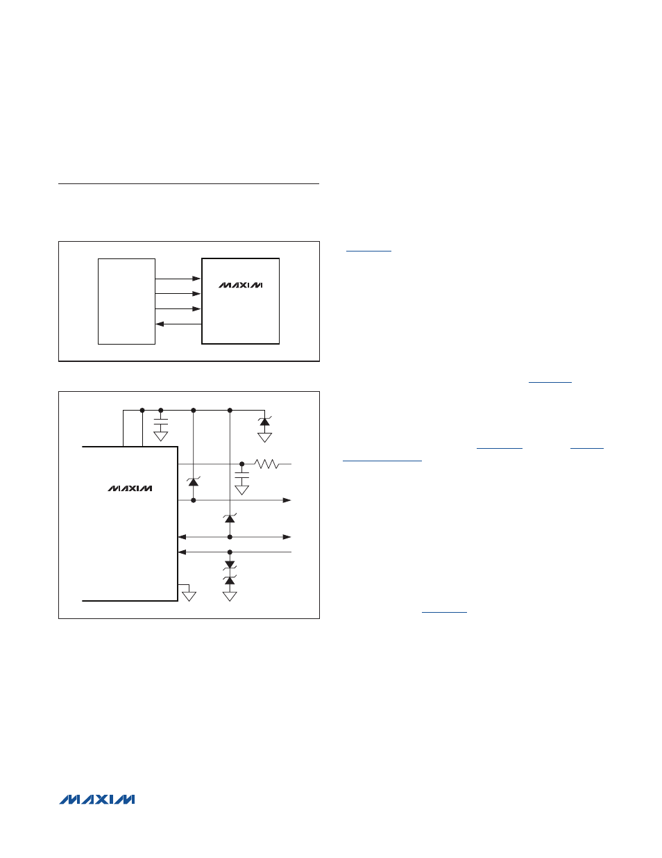
Transient Protection
Inductive load switching, surges, and bursts create high
transient voltages. C/Q, DO, and DI should be protected
against high overvoltage and undervoltage transients.
Positive voltage transients on C/Q, DO, and DI must be
limited to +55V relative to GND and negative voltage tran-
sients must be limited to -55V (relative to V
CC
) on DO and
C/Q and to -55V (relative to GND) on DI.
suitable protection using TVS diodes to meet both the
IEC 61000-4-4 burst and IEC 61000-4-5 surge testing.
Other protection schemes may also be suitable.
To protect against large transients at V
CC
, insert a
lowpass filter on V
CC
(see
and the
External Power
The device is powered by V
CC
and the 5V regulator, V
5
.
V
L
is a reference voltage input to set the logic levels of
the microcontroller interface. The logic and SPI interface
are operational when V
5
and V
L
are present even if V
CC
is not present.
The V
P
output provides a reverse-polarity-protected volt-
age one diode drop below V
CC
and can be used for sup-
plying external circuitry, like power supplies.
Connect LDOIN to V
5
to power the V
5
input with an
external supply (
). This configuration disables
operation of the internal 5V regulator and reduces power
consumption.
Figure 12. UART Interface
Figure 13. MAX14821 Operating Circuit with TVS Protection
MICROCONTROLLER
TXQ
GPO
TXC
TX
TXEN
RTS
RX
RX
MAX14821
MAX14821
0.8Ω
1μF
1μF
V
CC
LDOIN
DO
1/2
SDC36C
1/2
SDC36C
GND
C/Q
1/2
SDC36C
SDC36C
DI
V
P