Velleman HAM263D User Manual
Page 12
HAM263D
03 (15/11/2013)
VELLEMAN
12
•
show the faulty zone(s) during disarmed condition with user code
•
arm system instantly without delay
•
clear the alarm memory of the whole system or only specific sections
•
initiate dynamic battery test at anytime during disarmed mode
•
initiate a 5-second operation of both timing and latch output relays to test the connected
siren/strobe light
•
system code for direct access to programming mode in case the master code is forgotten
•
fully Compatible with HAM263D alarm systems
•
up to 4 keypads can be connected to the alarm system (HAM263D)
•
extra keypads have the exact same functionality as the master keypad
•
simply connect extra keypads in parallel with the master keypad
•
long connection distance possible, up to 500 metres
5.3
Installation
•
This keypad should be installed and serviced by a qualified person only.
•
Choose an easily accessible location where the keypad is protected from harsh environmental
conditions such as rain and bright sunlight, and away from heat producing devices.
•
Have a qualified person installing the electrical leads (4) that are necessary for the connection of
the keypad to the master control unit.
•
Remove the keypad from the mounting frame by removing the screw at the bottom and pulling
gently forward.
•
Mount the mounting frame over the leads coming from the master control unit. Do not damage
the leads when doing this.
•
Remove the back cover of the keypad by removing the screws at the four corners.
•
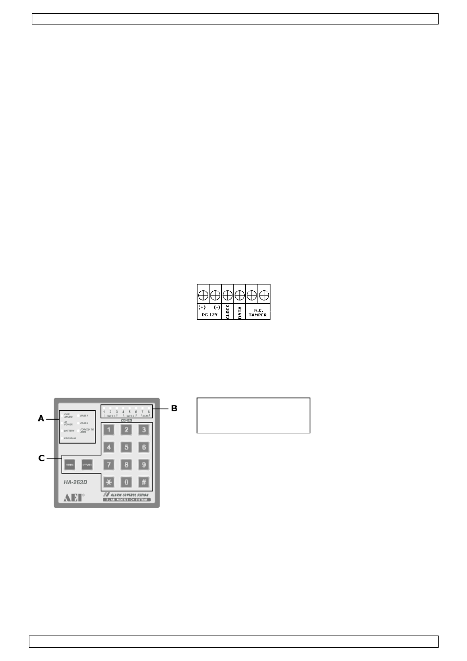
Make sure there is no power on the leads. Connect the leads to the connector block in the keypad
as indicated on the PCB.
•
It is also possible to install a tamper switch (not included).
•
Re-mount the back cover with the 4 screws.
•
Place the keypad back in the mounting frame. Make sure the cabling is not damaged in the
process. Remount the screw at the bottom.
•
Apply power to the leads (via the master control unit).
•
There are no user-serviceable parts. Contact your dealer for spare parts if necessary.
5.4
Keypad description
A. General status LEDs
B. Zone status LEDs
C. Control key buttons