Velleman HAM263D User Manual
Page 10
HAM263D
03 (15/11/2013)
VELLEMAN
10
e.
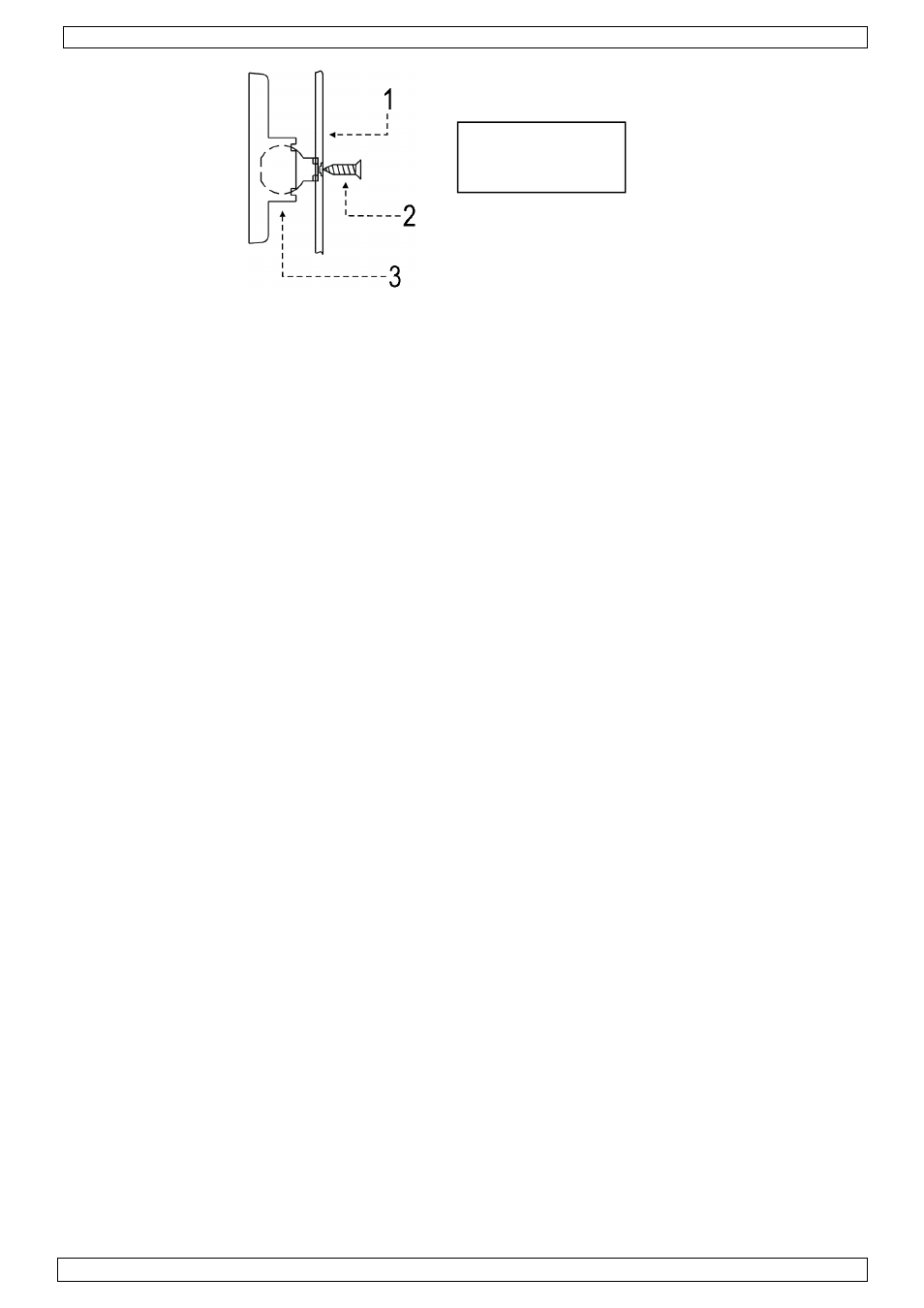
Wiring and Finishing
•
Fix the PCB back onto the rear cover.
•
Connect the wiring to the terminal block.
•
Place the front cover onto the rear cover and fix with the screw. Make sure you hear the tamper
switch clicking. Align the detector.
3.1.5
Walk test
•
Walk test can be performed after the power-up display expired - the alarm LED is flashing during
the power-up period - to test the detector over the entire protected area to verify proper
operation of the unit.
•
Walk into the protected area at a rate of one step per second across the protection beams and
observe the LED.
•
Alarm is triggered when the detector is tripped under standard alternate polarity signal
processing at normal condition.
•
The harsh condition requires the detector to be tripped twice within ten seconds under double
alternate polarity signal processing.
3.1.6
Technical specifications
Current Consumption
15mA @ 12VDC
Operating Voltage
8 ~ 16VDC, 12VDC nominal
Detection Method
PIR with alternate polarity processing
Power-up Delay
2 minutes with flashing LED
Alarm Period
2 ~ 3s
Alarm Output
NO or NC contact with 10Ω in-line resistor
Walk Test LED
alarm indicator, enable-disable selectable
Pulse Counting
normal response or 2 pulses within 10s
Tamper Switch
NC contact with 10Ω in-line resistor
Operating Temperature
-10°C ~ 55°C
Humidity
95% non-condensing
Dimensions
105 x 60 x 42mm
Weight
82g
3.2
Panic button (HAA60)
The panic button is a momentary contact switch that can be used as either a normally closed (NC)
or a normally open (NO) contact. It should be wired as part of zone 8, as this zone offers 24 hour
protection and can only be disabled by putting the whole system in standby-mode. Mount the panic
button in a dry and easily accessible location. The cabling from the master control unit as well as the
panic button should be installed by a qualified person.
•
Remove the front cover
•
Connect the wires coming from the master control unit. The type of contact (NC or NO) is
indicated on the housing.
•
Mount the panic button with the included screws.
•
Put the front cover on the mounted part and push until in snaps into place. Once mounted it is
very difficult to remove, so make sure the writing on the button is in the correct position…
•
Test to make sure everything functions as intended.
1. Rear cover
2. Fixing screw
3. Swivel bracket