Inter-axle differential lockout – Spicer Tandem Drive Axle Dual Range & Double Planetary 34,000-45,000 lbs User Manual
Page 68
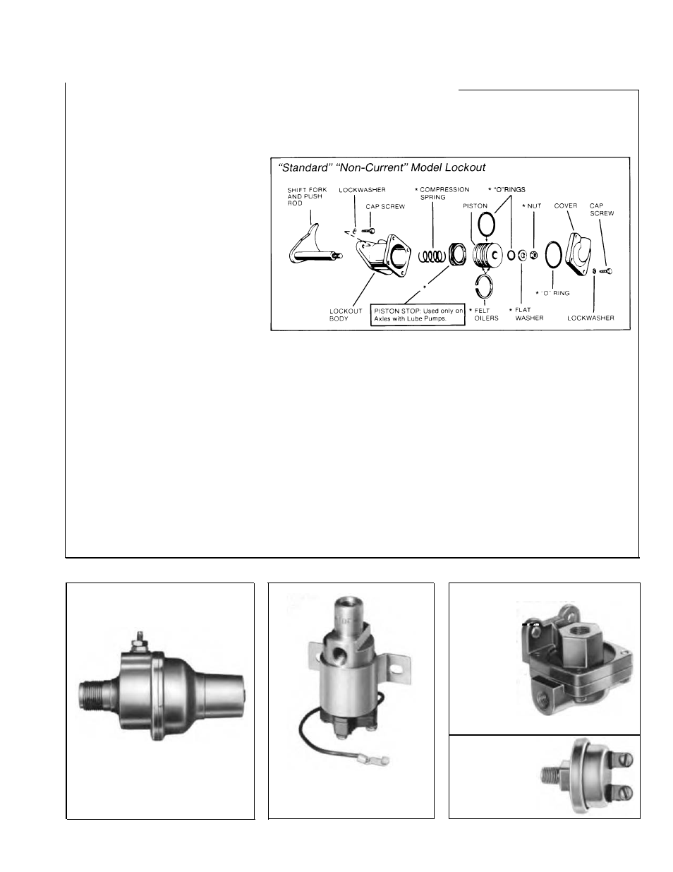
Inter-Axle Differential Lockout
(with Interlock Control Valve)
(straight-air type)
Lockout Cylinder
Disassemble Cylinder.
1.
Remove cap screws, lockwash-
ers, cover assembly and "O" ring,
2.
Remove hex-nut piston and
"O" rings.
3.
Remove body cap screws and
lockwashers, then remove body
and piston as an assembly.
Assemble Cylinder.
1.
Apply gasket compound to
mounting surface on power divider
cover.
2.
Install lockout body. Secure
with cap screws and lockwashers.
Torque cap screws to 48-56 ft-lbs.
(65-76 Nm).
NOTE:
Before installation, soak
piston felt oilers in SAE 30 engine
oil and lubricate "O" rings with a
high-viscosity silicone oil or barium
grease "O" ring lubricant.
3.
Install felt oilers and "O" ring on
piston.
Axles with Lube Pump:
Before
installing piston, place piston stop
at base of lockout body.
4.
Install compression spring over
shift fork push rod. Install piston in
body. Install "O" ring over push rod
and in piston. Install hex-nut piston
and tighten to 20-26 ft-lbs. (27-35
N«m). Install "O" ring on piston.
5.
Install "O" ring in lockout body cover. Install cover assembly and
secure with cap screws and lockwashers. Torque cap screws to
96-108 IN-LBS. (10-12 N«m).
6.
Adjust interlock control valve.
Interlock Control Valve
Repair and Replacement.
Replace faulty valve as an assembly,
Remove Valve.
1.
Loosen locknut and unscrew valve body from cylinder cover.
Install and Adjust Valve.
NOTE:
If button is not assembled to valve stem, install as follows: Insert
valve stem to full depth of the button. Lock in place with set screw. Torque
set screw to 6 IN-LBS. (0.7 Nm).
1.
With button assembled to valve, install locknut and Iockwasher on
valve body. With lockout cylinder exhausted, screw the valve assembly
into the lockout cylinder cover until the valve is seated on hex-nut piston.
2.
To adjust, unscrew control valve until the valve air-delivery port is
aligned with the lockout cylinder air-inlet port.
NOTE: Do not unscrew
valve more than 360
o
.
Lock the valve in place with locknut. Torque locknut to 35 IN-LBS.
(3.9 Nm).
Speedometer Adapter
The speedometer adapters are
lubricated and sealed for life of
the unit. No maintenance is
required. Replace a faulty unit.
Solenoid
Valve
Replace solenoid valve as an
assembly. The valve should
not be serviced.
Quick Release Valve
ã
If quick release
valve fails to
operate prop-
erly, it may be
repaired as
follows: Dis-
assemble valve.
Inspect valve
body, valve seat
and spring (if
used) for evi-
dence of faulty operation.
Replace
faulty parts, then reassemble valve.
,. .. .
Pressure
Switch
Replace pressure
switch as an assembly.
69