Axle shift components. i, Model lockout, Standard” "non-current” model lockout overhaul – Spicer Tandem Drive Axle Dual Range & Double Planetary 34,000-45,000 lbs User Manual
Page 67: Retrofit “non-current” to “current
Axle Shift Components.
I
Retrofit “Non-Current” to “Current”
Model Lockout
The “current” model (only as an
assembly) is interchangeable with
the “non-current” lockout. The
original shift fork and push rod can
be used for either model lockout
and need not be replaced.
Retrofit Kits are available to convert
the “non-current” model to the
“current” lockout. Parts (except the
shift fork), included in these kits are
2.
Assemble and install “current”
shown in the illustration on the
lockout following instructions on
preceding page. For additional
preceding page.
information, refer to Spicer Parts
NOTE:
Do not use mounting screws
Books (see inside back cover).
from “non-current” model. They
are too long to use with the new
1.
Disassemble and remove
“current” model.
“non-current” lockout. Refer to
instructions below.
“Standard” "Non-Current” Model Lockout Overhaul
Service Parts Availability.
The
“non-current” lockout assembly,
body, piston and body cover are
no longer available. If any of these
items are not serviceable, replace
lockout with the new “current”
model per instructions above. For
other parts, a Service Parts Kit
(see illustration) is available to
service the “non-current” lockout.
Disassemble and Remove Lockout
1.
Remove cap screws and
lockwashers fastening cover to the
body. Remove cover and “O’’ ring.
2.
Remove nut, flat washer and
“O’’ ring from push rod.
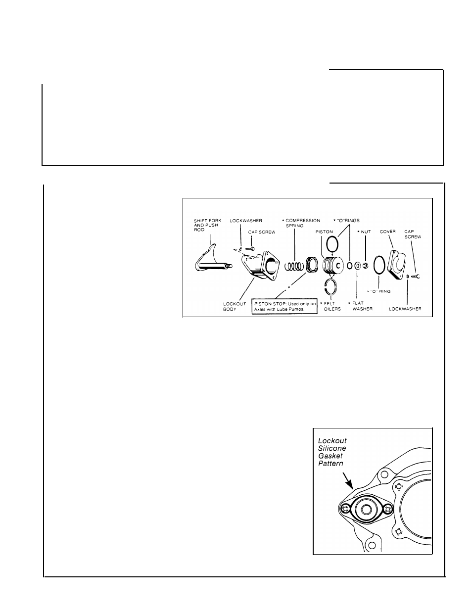
“Standard” “Non-Current” Model Lockout
*Asterisk Identifies parts included in Service Kit 277207
NOTE: Axles with Lube Pumps:
These axle models are equipped with a
piston stop located at base of piston.
reinstalled in reassembly.
3.
Remove body cap screws and
lockwashers, then remove body
and piston as an assembly. Remove
“O’’ ring and felt oilers from the
piston.
It is important that this stop be
NOTE:
The shift fork and push rod
cannot be removed with power
divider cover installed (see Power
Divider instructions).
Assemble and Install Lockout
With shift fork and sliding clutch
installed in power divider cover,
assemble and install lockout as
follows.
1.
Apply silicone gasket compound
to mounting surface on power
divider cover. See illustration.
2.
Install lockout body. Secure with
cap screws and lockwashers.
Torque cap screws to 48-56 Ibs.-ft.
(65-76 N•m).
NOTE:
Before installation, soak
piston felt oilers in SAE 30 engine
oil and lubricate “O’’ rings with a
high-viscosity silicone oil or barium
grease “O’’ ring lubricant.
3.
Install felt oilers and large
“O” ring on piston.
Axles with Lube Pump.
Before
installing piston, place piston stop
at base of lockout body.
4.
Install compression spring over
shift fork push rod. Install piston in
body and secure with “O” ring, flat
washer and nut. Torque nut to
20-26 Ibs.-ft. (27-35 N•m).
5. install “O’’ ring in lockout body
cover. Install cover and secure with
cap screws and lockwashers.
Torque cap screws to 96-108
LBS.-IN (10-12 N•m).
68