Install power divider on differential carrier – Spicer Tandem Drive Axle Dual Range & Double Planetary 34,000-45,000 lbs User Manual
Page 33
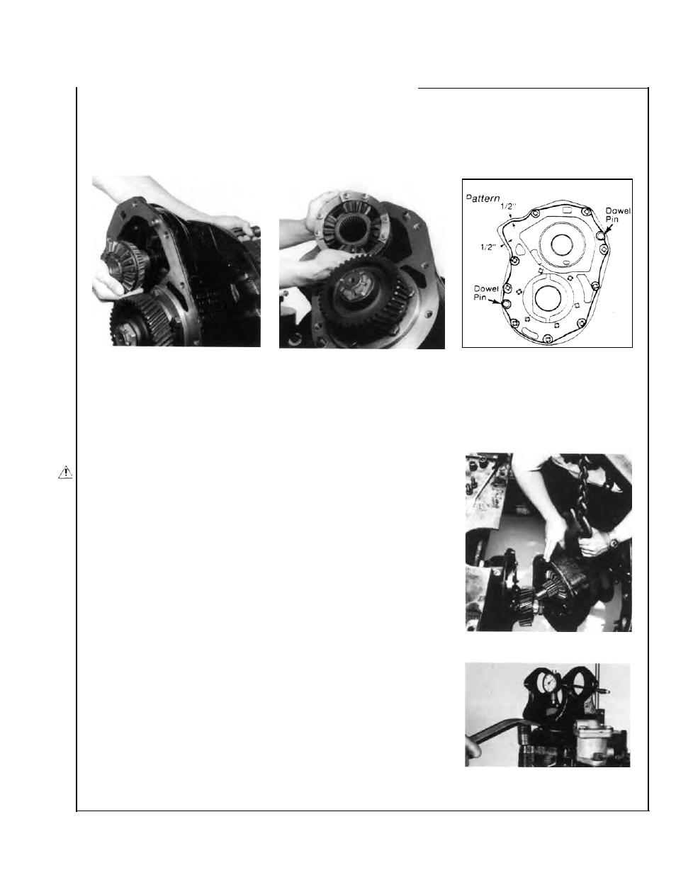
Install Power Divider on Differential Carrier
ïwith carrier assembled to axle housing)
NOTE:
Lubricate all parts before installation.
1. Axle Housing Covet and Output Shaft Bearing Parts.
If removed,
install these parts following instructions on page 31.
-.
Silicone Gasket Compound
2. Output Shaft.
If removed,
lubricate "O" rings, then install
shaft assembly in differential car-
rier and housing cover. Lubricate
seal lip. Make sure yoke is clean
and dry, then install yoke, flat
washer and self-locking nut.
Torque nut to 480-600 ft.-lbs.
(650-813 Nm),
NOTE:
Late Model Axles may be
equipped with a spring and thrust
button mounted in end of output
shaft. (see page 74).
3. Inter-axle Differential.
Install
this assembly on output shaft side
gear (with nuts facing away from
side gear).
4. Power Divider Assembly.
Use
silicone rubber gasket compound
on differential carrier mating sur-
face as shown in the illustration.
NOTE:
Compound will set in 20
minutes. Install power divider be-
fore compound sets or reapply.
CAUTION:
DURING INSTALLATION OF POWER DIVIDER, THE
INTER-AXLE DIFFERENTIAL MAY FALL FROM CARRIER. EXERT
CAUTION TO PREVENT DAMAGE OR INJURY.
5.
Make certain dowel pins are installed in carrier (see drawing above),
then install power divider assembly.
Use a transmission jack or a chain hoist and sling (see photo).
During installation, rotate input shaft to engage input shaft splines with
inter-axle differential. After installation, again rotate input shaft to check
for correct assembly. Output shaft should turn when input shaft is
rotated.
6.
Install power divider cover cap screws and lockwashers. On pump
models only, install socket-head cap screw in correct location (see
drawing on preceding page). Torque cap screw to 110-125 ft.-lbs.
(149-170 Nm).
7. Check and Adjust Input Shaft Play.
With power divider assembled
to differential carrier. Check end play with dial indicator. If necessary
adjust end play (see page 19 or Service Bulletin Supplement Page 74).
After input shaft end play is within specifications complete assembly
procedure follows:
8.
Connect drivelines. Connect lockout air line.
9.
Fill axle to proper lube level (see Lubrication Section).
IMPORTANT:
When axle has been disassembled or housing, gears, axle
shafts or wheel equipment replaced, check axle assembly for proper
differential action before operating vehicle. Wheels must rotate freely
and independently.
Installing Power
Divider Assembly
with Chain Hoist and Sling.
Measuring Input Shaft End Play
with Dial Indicator.
33