Power divider overhaul, Assemble power divider (cont'd) – Spicer Tandem Drive Axle Dual Range & Double Planetary 34,000-45,000 lbs User Manual
Page 40
Power Divider Overhaul
Assemble Power Divider (Cont'd)
5.
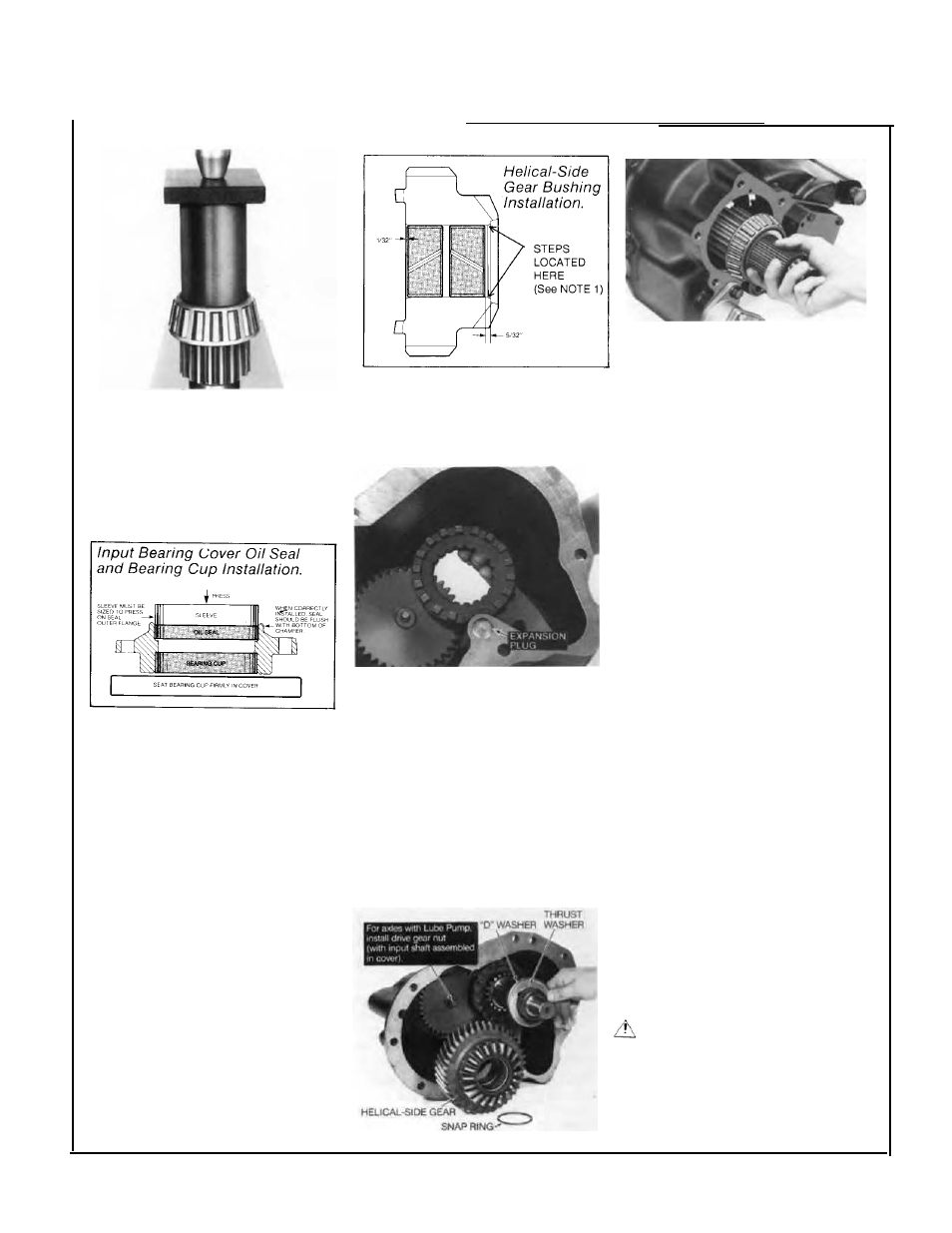
Press bearing cone on input
shaft.
IMPORTANT:
To prevent bearing
damage, be careful to use sleeve
that only contacts the inner race
of bearing cone.
SEAL INSTALLATION
IMPORTANT:
Before installing
seal, refer to page 15 for service
information on SeaIs, Yokes &
Slingers.
6.
Press oil seal in cover using a
seal driver or suitable sleeve.
Press bearing cup in input
bearing cover.
IMPORTANT:
For correct cup
installation, use appropriate
sleeve. Take care to make sure
cup is not cocked and is firmly
seated all around.
NOTE 1:
Helical Gears made after
1/3/95 have a "step" at the end of
Inner Bore. Bushings must be in-
stalled from the Curvic Tooth side of
the Helical Gear inward towards this
step. Press bushing flush against
the shoulder of the step.
7.
Install bronze bushings in
helical-side gear.
8. NOTE:
Check expansion plug in
power divider cover (see photo
above) to make sure it is in place
and firmly seated. If loose, seat by
tapping with a hammer. Replace
plug if necessary.
Assemble lockout shift fork and
sliding clutch with clutch teeth
facing the helical-side gear, then
install this assembly in power
divider cover.
NOTE:
At this point in reassembly,
assemble and install lockout (see
Shift System Section).
9.
Slide input shaft and bearing
assembly into power divider cover
from the front side. Engage shaft
splines in lockout clutch.
Install bearing spacer on input
shaft (used only on D340, 380,
380-P, 400-P). Temporarily install
input bearing cover assembly, cap
screws and lockwashers.
NOTE:
Do not install any shims
under bearing cover at this time.
Correct shim pack will be deter-
mined after the power divider is
installed on differential carrier
(Refer to "Adjust Input Shaft End
play" page 42).
IMPORTANT: For Axles with
Spring and Thrust Button between
input shaft and output shaft:
For
preliminary adjustment of input
shaft end play, install a 0.045"
(0.024 mm) shim pack under
bearing cover (see Service
Bulletin Supplement, page 74).
Tighten bearing cover cap screws
finger-tight. Install input yoke, flat
washer and nut. Temporarily
tighten nut snugly.
10. lMPORTANT - Axles with
Lube Pump:
Install and tighten
lube pump drive gear locknut,
holding input shaft to secure gear.
Torque nut to 35-45 ft-lbs,
(47-61 Nm).
11.
Slide "D" washer over input
shaft up to base of sliding clutch
,.
splines.
NOTE:
Make sure flat part of
washer inside diameter engages
shaft properly.
Install bronze washer, Install
helical gear. Secure with snap ring.
WARNING:
SNAP RING IS
SPRING STEEL AND MAY POP
OFF. WEAR SAFETY GLASSES
WHEN INSTALLING.
12.
Install power divider cover
assembly on differential carrier
(see page 41).
40