Installation – American Magnetics 05100PS-430-601 Integrated Power Supply System User Manual
Page 32
14
Rev.
5
Installation
Power Requirements
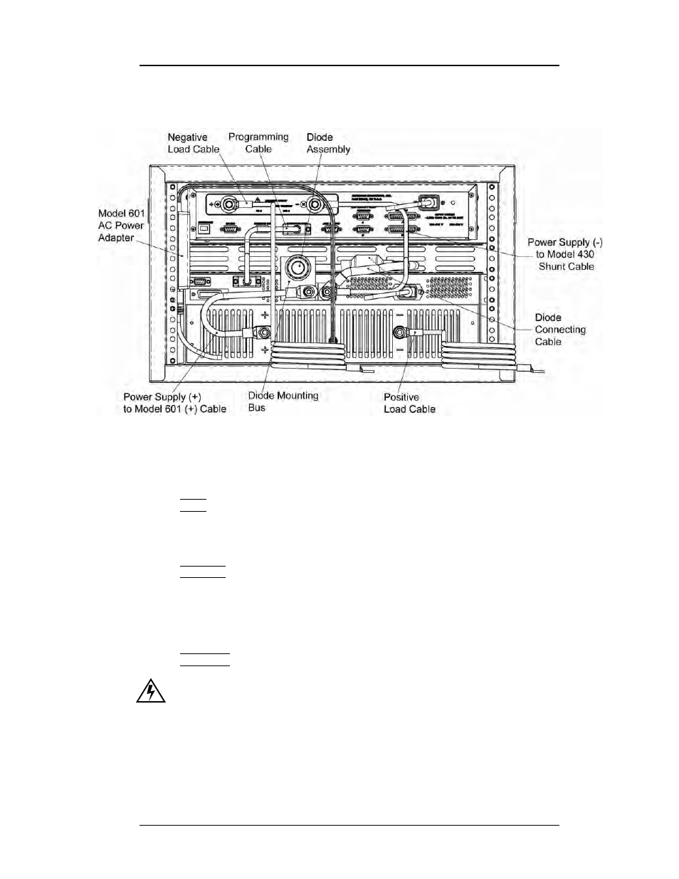
and Figure 2-2 on page 15 depict the 05100PS-430-601 integrated power
supply system interconnects.
Refer to Figure 2-2 on page 15. Ensure the cabling is connected in the
following manner:
Note
The use of locking hardware is recommended for all high-current
connections.
Caution
Do not overtighten the hardware on the interconnection terminals
(refer to specifications table on page 9 for torque limits).
Overtightening can result in damage to the terminals.
Warning
Ensure the protective diode is installed across the output terminals
of the power supply with the anode at the negative (–) terminal and
the cathode at the positive (+) terminal. Removal or omission of this
protective diode may cause serious injury to personnel and damage
to the power supply under loss of AC power conditions.
Figure 2-1.
Typical Model 05100PS-430-601 System Rack Interconnections