Toshiba TLPX10E User Manual
Page 25
25
Installation and
connection
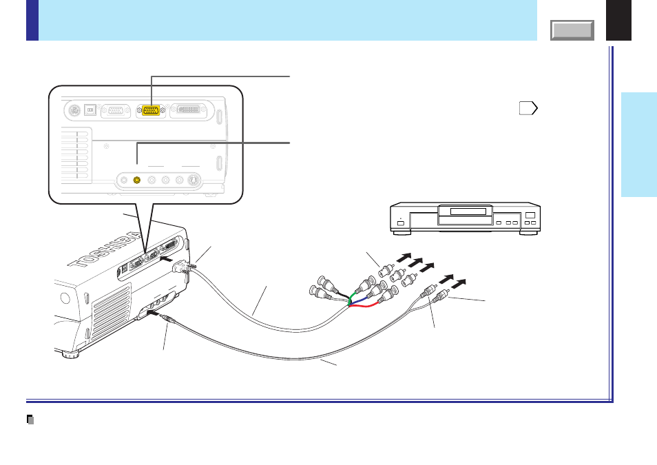
Connecting video equipment (continued)
Note
Some component video signal sources include the Y/C
B
/C
R
signals of a DVD player and the Y/P
B
/P
R
signals of high definition devices, etc.
You can project the picture from video equipment with component video output jack.
Check that the power for the projector and video equipment is off before connecting the cables.
USB
MONIT
OR OUT
COMPUTER IN 1
( Y/P
B/P
R
)
COMPUTER IN 2
CONTR
OL
S-VIDEO
VIDEO
VIDEO IN
R - A
UDIO
- L
AUDIO
IN
AUDIO
OUT
USB
MONITOR OUT
COMPUTER IN 1
( Y/P
B
/P
R
)
COMPUTER IN 2
CONTROL
S-VIDEO
VIDEO
VIDEO IN
R - AUDIO - L
AUDIO
IN
AUDIO
OUT
Video equipment with component
video output jack. (DVD player, etc.)
COMPUTER IN 1 Connector
For use as both analog RGB1 input and Y/P
B
/P
R
input. At shipping from
factory, it is set for use as analog RGB1 input.
Change the setting on the menu when using as Y/P
B
/P
R
input.
AUDIO IN jack
For use as both audio signals for RGB input (analog RGB1/analog
RGB2/digital RGB) and Y/P
B
/P
R
input.
Pin plug (red)
To audio output (R)
To AUDIO IN jack
To COMPUTER IN 1 connector
Be sure to connect in the proper
direction.
Adapter
BNC-pin
(Not supplied)
Audio cable (not supplied)
Monitor cable
Mini D-sub 15P-BNC
(Not supplied)
Pin plug (white)
To audio output (L)
(
Blue
) To P
B
(C
B
) video output
(
Green
) To Y video output
(
Red
) To P
R
(C
R
) video output