Back panel connectors – Intel Vig390s User Manual
Page 8
Vig390s Motherboard Manual V1.0
7
O
SSI ATX Power connector 24 way
KK
PCI3 PCI-X connector (64bit)
P
CPU1 FAN connector
LL
PCI5 PCI connector (32bit 5V)
Q
Northbridge Intel © E7525
MM
PCI2 PCI-Express x 16 connector
R
ATX 12V1 connector 6 way
NN
PCI1 PCI-Express x 4 connector
S
CPU 1 socket (mPGA604 pin socket
for Intel ® Xeon ™)
OO
WIFI proprietary connector (not
supported)
T
CPU 2 socket (mPGA604 pin socket
for Intel ® Xeon ™)
PP
SMBus connector
U
CPU 2 FAN connector
Second serial port header
V
Front Chassis Fan 1
RR
Power to motherboard LED
Note:
1. SATA 1 is to be used for Boot disk SATA 2 for data disk.
2. SATA RAID 0/1 is supported by Windows XP + SP1 and Windows 2000Pro + SP4.
3. Windows XP supports 2 CPU’s with hyperthread enabled, if 2 CPU’s are to be used with
Windows 2000Pro hyperthread must be disabled.
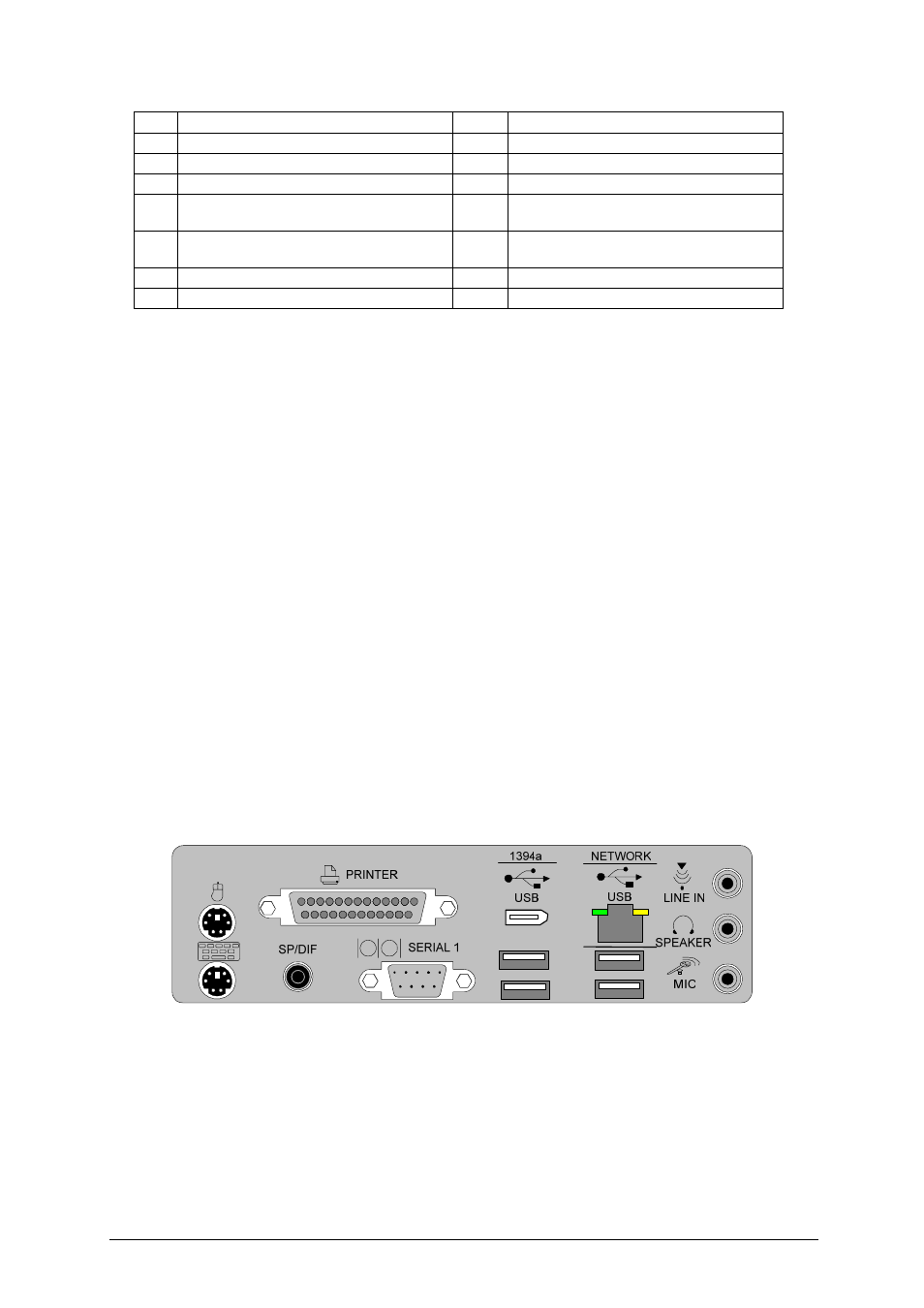
Back Panel Connectors
The motherboard external IO connectors are attached to a metallic I/O shield.
This shield serves several purposes:
• It protects the sensitive motherboard from any external EMC interference.
• It stops the computer from interfering with other electrical devices.
• It allows the motherboard to be easily upgraded in the future without having to
resort to buying a whole new case. Simply change the I/O shield to match the
motherboard.
The I/O shield provides external access to PS/2 keyboard and mouse connectors as
well as one serial port, one parallel port, two USB ports, one LAN Port and the audio
connectors.
Figure 2: I/O shield
Note:
Power to the computer should be turned off before a keyboard or mouse is
connected or disconnected.