Removing the top cover, Removing the pad and touch pad pcb, Removing the sd pcb – Matsushita CF-52AJYZDZM User Manual
Page 30
9-7
9.1.14.
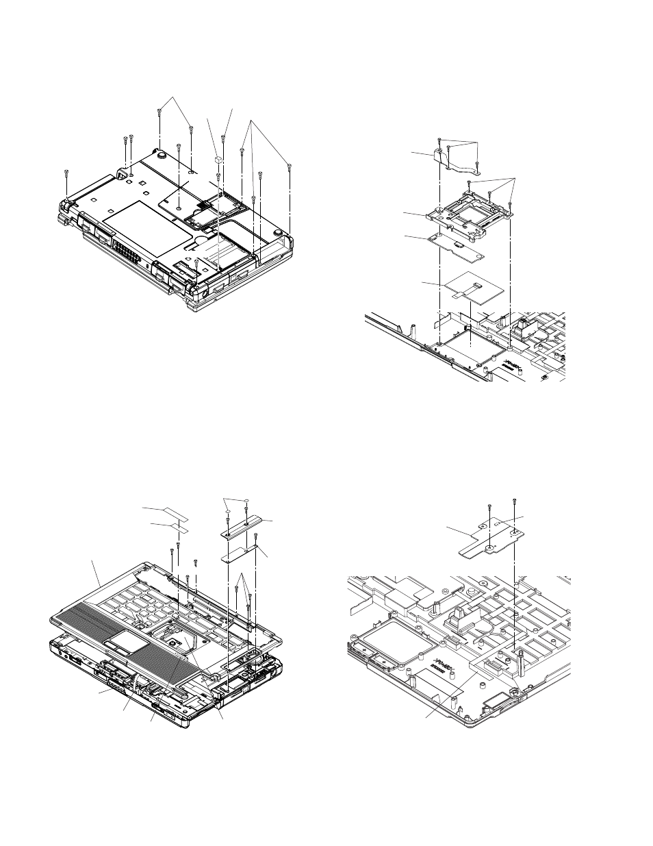
Removing the Top Cover
1. Remove the Gasket.
2. Remove the Screws
3. Turn the unit to the face, remove the Screw
five Screws
4. Remove the WP Sheet and Tape, and remove the Screw
5. Remove the two Screw Sheets.
Remove the two Screws
BT.
Remove the Screw
the BT UNIT PCB, and remove it.
6. Disconnect the FFC and KBD FPC from the Connec-
tors(CN23 and CN22), and lift up the Top Cover Ass’y and
remove it.
Screws
Screw
Screws
Screws
Screws
Screws
9.1.15.
Removing the Pad and TOUCH PAD
PCB
1. Remove the six Screws
2. Remove the Top Relay Plate and Pad Holder.
3. Remove the Pad and TOUCH PAD PCB.
Screws
9.1.16.
Removing the SD PCB
1. Remove the two Screws
2. Disconnect the FFC from the Connector(CN4300), and
remove the SD PCB.
Screws
Gasket
Screw
sheet
Cover
BT
BT UNIT
PCB
CN22
KBD FPC
CN23
FFC
WP sheet
Tape
Top cover ass'y
Top relay plate
Pad holder
TOUCH PAD
PCB
Pad
SD PCB
FFC
CN4300