9 disassembly/reassembly, Disassembly instructions, Disassembly flowchart – Matsushita CF-52AJYZDZM User Manual
Page 24
9-1
9 Disassembly/Reassembly
Note:
Power off the computer. Do not shut down to the Suspend or hibernation mode.
Do not add peripherals while the computer is in the Suspend or hibernation mode; abnormal operation may result.
9.1.
Disassembly Instructions
9.1.1.
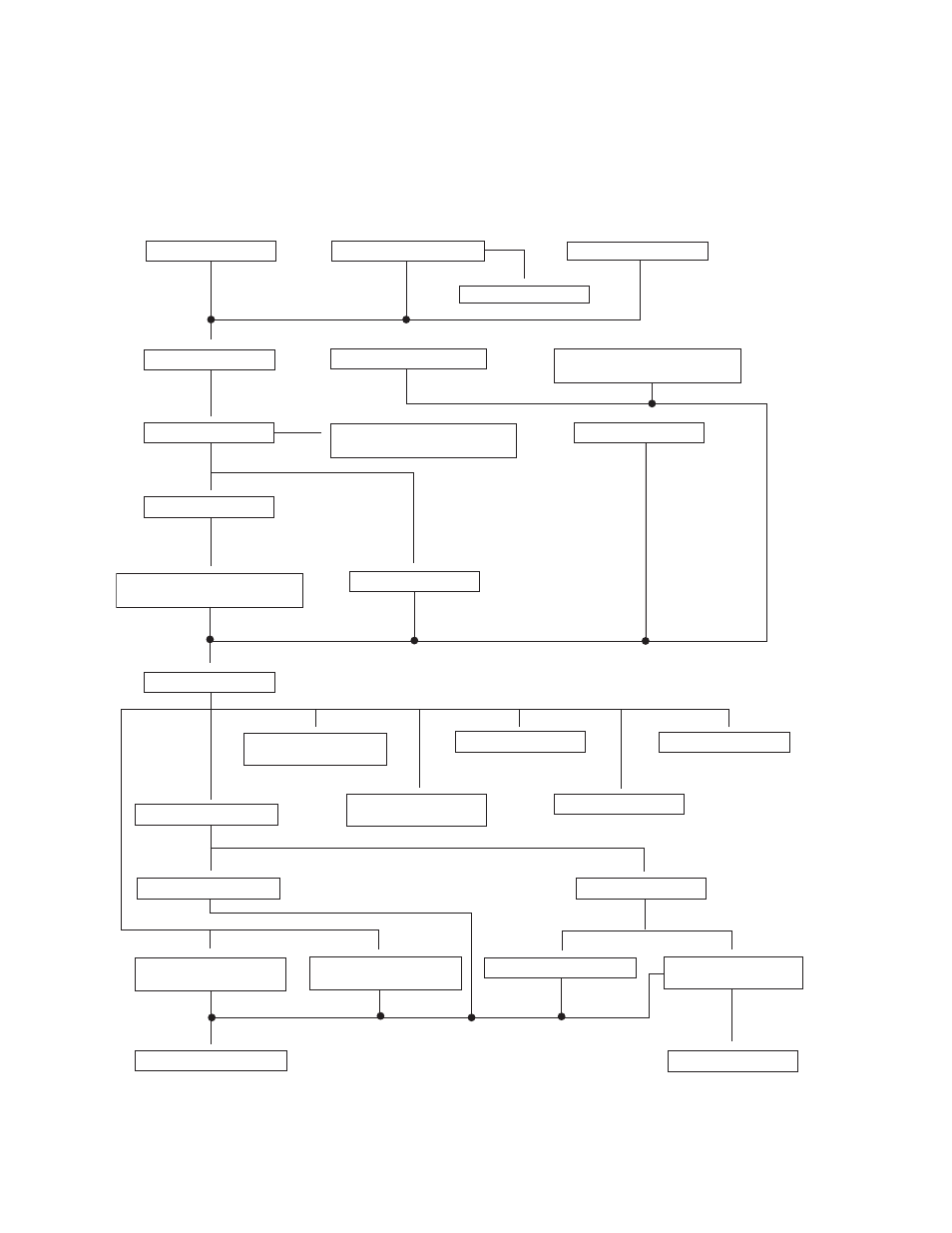
Disassembly Flowchart
The chart below shows the various parts which should be removed in order to remove the parts that are to be replaced.
Parts can be replaced efficiently be following the disassembly
steps in the chart.
9.1.3.1. Battery Pack
9.1.3.2. HDD Mounting Kit
9.1.3.3. DVD Multi Drive
9.1.4. HDD
9.1.5. Tilt Panel Ass'y
9.1.6. DIMM Memory Card
9.1.7. ROBSON Cover, Wireless
LAN Module and BIOS PCB
9.1.8. Display Unit
9.1.9. LCD Unit, Inverter Ass'y,
and ANTENNA PWB L, R
9.1.10. Handle Ass'y
9.1.12. SW LED MDC PCB,
Speaker L and R
9.1.13. Keyboard
9.1.14. Top Cover
9.1.15. Pad and TOUCH
PAD PCB
9.1.16. SD PCB
9.1.17. WWAN PCB
9.1.18. AUDIO PCB
9.1.19. PWR BATTERY
LED PCB
9.1.20. KBD Earth Plate
9.1.21. Hinge Support R
9.1.22. Fan Ass'y
9.1.23. Hinge support L
and MP Hold Plate
9.1.24. Battery Connector
Ass'y
9.1.25. SC RELAY PCB
and HDD Hold Plate
9.1.26. Heat Sink Ass'y
9.1.27. SERIAL PCB
9.1.28. MAIN HIGH PCB
9.1.11. Modem