6 monitor rom, 7 random-access memory (ram), Monitor rom – Freescale Semiconductor MC68HC908MR32 User Manual
Page 37: Random-access memory (ram)
Monitor ROM
MC68HC908MR32 • MC68HC908MR16 Data Sheet, Rev. 6.1
Freescale Semiconductor
37
2.6 Monitor ROM
The 240 bytes at addresses $FE10–$FEFF are reserved ROM addresses that contain the instructions for
the monitor functions. See
2.7 Random-Access Memory (RAM)
Addresses $0060–$035F are RAM locations. The location of the stack RAM is programmable. The 16-bit
stack pointer allows the stack to be anywhere in the 64-Kbyte memory space.
NOTE
For correct operation, the stack pointer must point only to RAM locations.
Within page zero are 160 bytes of RAM. Because the location of the stack RAM is programmable, all page
zero RAM locations can be used for input/output (I/O) control and user data or code. When the stack
pointer is moved from its reset location at $00FF, direct addressing mode instructions can access
efficiently all page zero RAM locations. Page zero RAM, therefore, provides ideal locations for frequently
accessed global variables.
Before processing an interrupt, the central processor unit (CPU) uses five bytes of the stack to save the
contents of the CPU registers.
NOTE
For M68HC05 and M1468HC05 compatibility, the H register is not stacked.
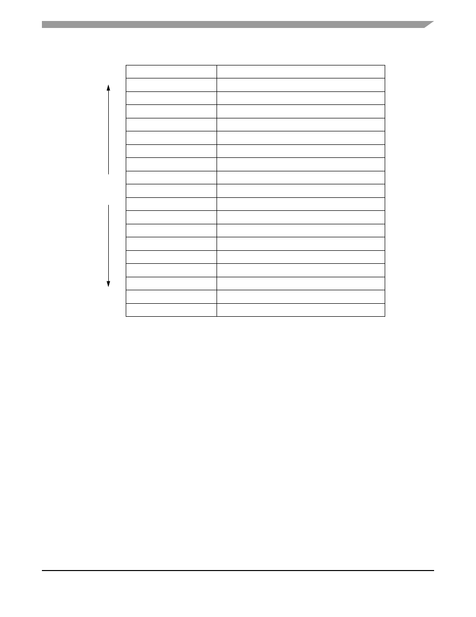
$FFEE
PWMMC vector (high)
$FFEF
PWMMC vector (low)
$FFF0
FAULT 4 (high)
$FFF1
FAULT 4 (low)
$FFF2
FAULT 3 (high)
$FFF3
FAULT 3 (low)
$FFF4
FAULT 2 (high)
$FFF5
FAULT 2 (low)
$FFF6
FAULT 1 (high)
$FFF7
FAULT 1 (low)
$FFF8
PLL vector (high)
$FFF9
PLL vector (low)
$FFFA
IRQ vector (high)
$FFFB
IRQ vector (low)
$FFFC
SWI vector (high)
$FFFD
SWI vector (low)
High
$FFFE
Reset vector (high)
$FFFF
Reset vector (low)
Table 2-1. Vector Addresses (Continued)
Address
Vector
Priority