Figure 17-2, Is a block dia, Shows the timb st – Freescale Semiconductor MC68HC908MR32 User Manual
Page 237: Figure 17-2. timb block diagram, Figure 17-3. timb i/o register summary
Functional Description
MC68HC908MR32 • MC68HC908MR16 Data Sheet, Rev. 6.1
Freescale Semiconductor
237
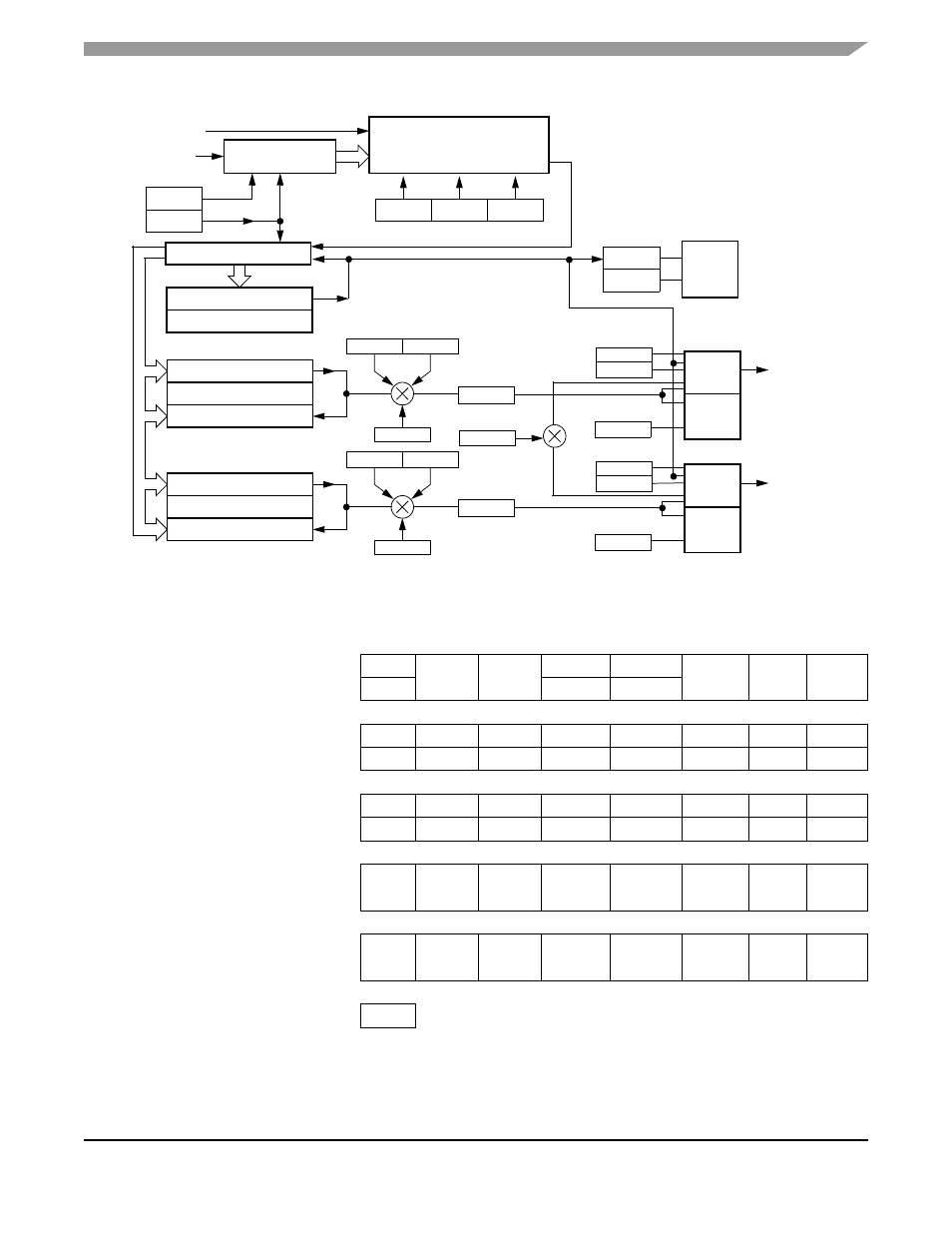
Figure 17-2. TIMB Block Diagram
Addr.
Register Name
Bit 7
6
5
4
3
2
1
Bit 0
$0051
TIMB Status/Control Register
(TBSC)
Read:
TOF
TOIE
TSTOP
0
0
PS2
PS1
PS0
Write:
0
TRST
R
Reset:
0
0
1
0
0
0
0
0
$0052
TIMB Counter Register High
(TBCNTH)
Read:
Bit 15
Bit 14
Bit 13
Bit 12
Bit 11
Bit 10
Bit 9
Bit 8
Write:
R
R
R
R
R
R
R
R
Reset:
0
0
0
0
0
0
0
0
$0053
TIMB Counter Register Low
(TBCNTL)
Read:
Bit 7
Bit 6
Bit 5
Bit 4
Bit 3
Bit 2
Bit 1
Bit 0
Write:
R
R
R
R
R
R
R
R
Reset:
0
0
0
0
0
0
0
0
$0054
TIMB Counter Modulo Register
High (TBMODH)
Read:
Bit 15
Bit 14
Bit 13
Bit 12
Bit 11
Bit 10
Bit 9
Bit 8
Write:
Reset:
1
1
1
1
1
1
1
1
$0055
TIMB Counter Modulo Register
Low (TBMODL)
Read:
Bit 7
Bit 6
Bit 5
Bit 4
Bit 3
Bit 2
Bit 1
Bit 0
Write:
Reset:
1
1
1
1
1
1
1
1
R
= Reserved
Figure 17-3. TIMB I/O Register Summary
PRESCALER
PRESCALER SELECT
TCLK
INTERNAL
16-BIT COMPARATOR
PS2
PS1
PS0
16-BIT COMPARATOR
16-BIT LATCH
TCH0H:TCH0L
MS0A
ELS0B
ELS0A
PTE1
TOF
TOIE
INTER-
CHANNEL 0
TMODH:TMODL
TRST
TSTOP
TOV0
CH0IE
CH0F
CH0MAX
MS0B
16-BIT COUNTER
BUS CLOCK
PTE0/TCLKB
PTE1/TCH0B
PTE2/TCH1B
LOGIC
RUPT
LOGIC
INTER-
RUPT
LOGIC
16-BIT COMPARATOR
16-BIT LATCH
TCH1H:TCH1L
MS1A
ELS1B
ELS1A
PTE2
CHANNEL 1
TOV1
CH1IE
CH1F
CH1MAX
LOGIC
INTER-
RUPT
LOGIC