3 manual mode, Manual mode – Freescale Semiconductor MC68HC908MR32 User Manual
Page 140
Pulse-Width Modulator for Motor Control (PWMMC)
MC68HC908MR32 • MC68HC908MR16 Data Sheet, Rev. 6.1
140
Freescale Semiconductor
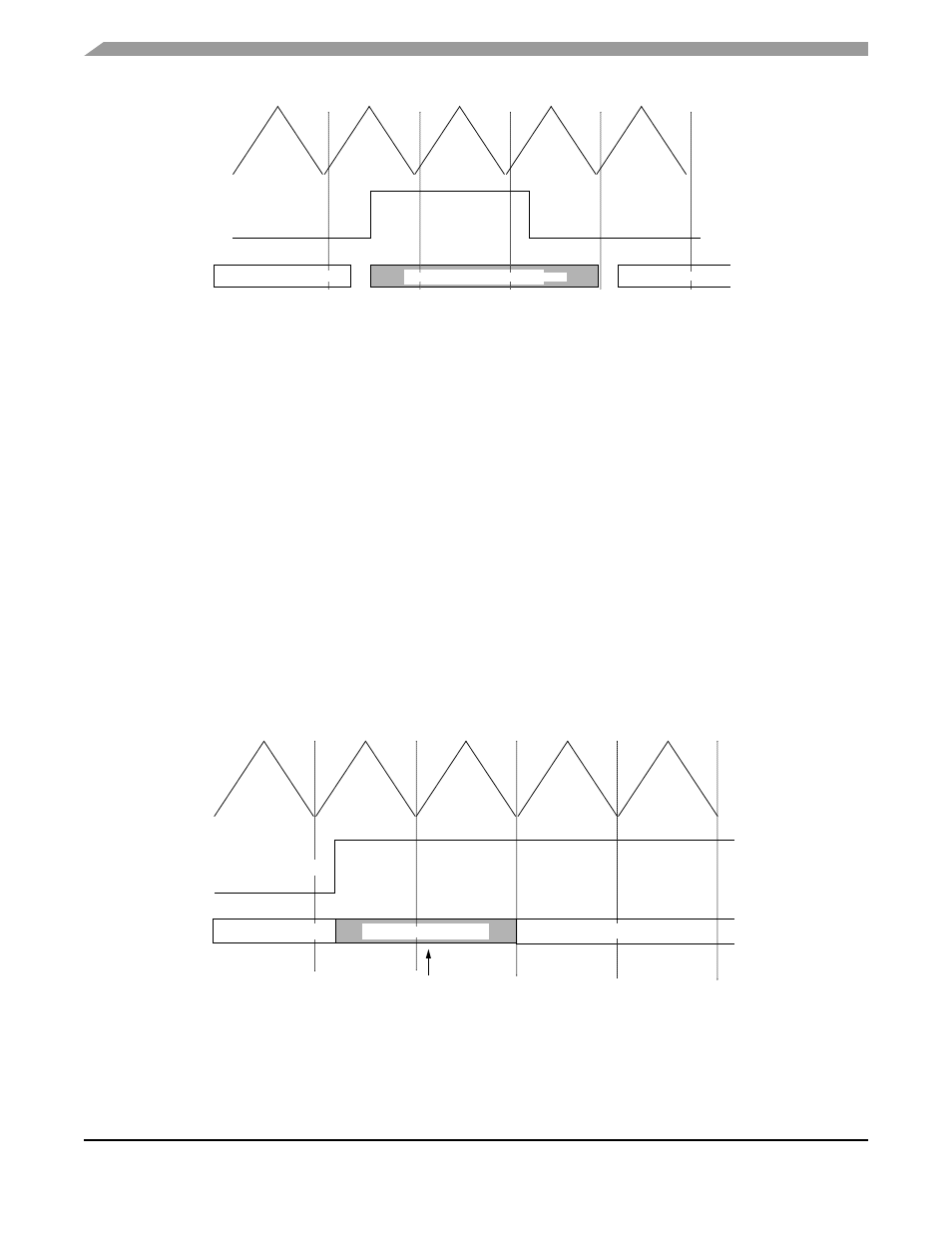
Figure 12-28. PWM Disabling in Automatic Mode
IIf prior to a vector fetch, the interrupt request latch is cleared by one of the actions listed, a CPU interrupt
will no longer be requested. A vector fetch does not alter the state of the PWMs, the FFLAGx event flag,
or FINTx.
NOTE
If the FFLAGx or FINTx bits are not cleared during the interrupt service
routine, the interrupt request latch will not be cleared.
12.6.1.3 Manual Mode
In manual mode, the PWM(s) are disabled immediately once a filtered fault condition is detected (logic
high). The PWM(s) remain disabled until software clears the corresponding FFLAGx event bit and a new
PWM cycle begins. In manual mode, the fault pins are grouped in pairs, each pair sharing common
functionality. A fault condition on pins 1 and 3 may be cleared, allowing the PWM(s) to enable at the start
of a PWM cycle regardless of the logic level at the fault pin. See
. A fault condition on pins 2
and 4 can only be cleared, allowing the PWM(s) to enable, if a logic low level at the fault pin is present at
the start of a PWM cycle. See
The function of the fault control and event bits is the same as in automatic mode except that the PWMs
are not re-enabled until the FFLAGx event bit is cleared by writing to the FTACKx bit and the filtered fault
condition is cleared (logic low).
Figure 12-29. PWM Disabling in Manual Mode (Example 1)
PWM(S) ENABLED
PWM(S) ENABLED
PWM(S) DISABLED (INACTIVE)
FILTERED FAULT PIN
PWM(S) ENABLED
PWM(S) ENABLED
PWM(S) DISABLED
FFLAGX CLEARED
FILTERED FAULT PIN 1 OR 3