3 timebase, 1 resolution, Timebase – Freescale Semiconductor MC68HC908MR32 User Manual
Page 120: Resolution
Pulse-Width Modulator for Motor Control (PWMMC)
MC68HC908MR32 • MC68HC908MR16 Data Sheet, Rev. 6.1
120
Freescale Semiconductor
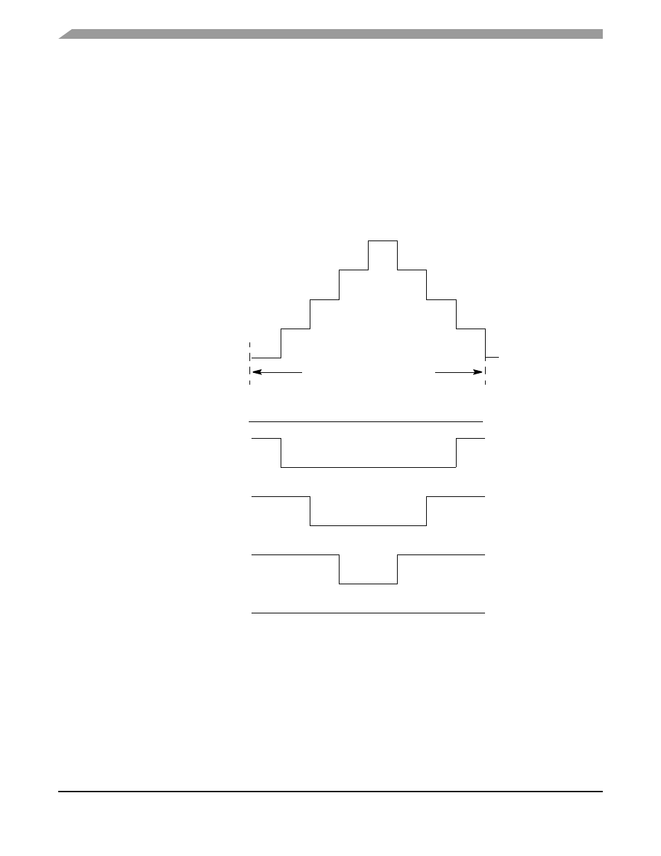
12.3 Timebase
This section provides a discussion of the timebase.
12.3.1 Resolution
In center-aligned mode, a 12-bit up/down counter is used to create the PWM period. Therefore, the PWM
resolution in center-aligned mode is two clocks (highest resolution is 250 ns @ f
OP
= 8 MHz) as shown in
. The up/down counter uses the value in the timer modulus register to determine its maximum
count. The PWM period will equal:
[(timer modulus) x (PWM clock period) x 2].
Figure 12-4. Center-Aligned PWM (Positive Polarity)
UP/DOWN COUNTER
MODULUS = 4
PWM = 0
PWM = 1
PWM = 2
PWM = 3
PWM = 4
PERIOD = 8 X (PWM CLOCK PERIOD)
This manual is related to the following products: