Dp2s & dp4s serial connection – FEC DSP1500 (SAN3) User Manual
Page 65
PAGE 6-3
enFORCE
Operation Manual
6.1.1 DP2S & DP4S Serial Connection
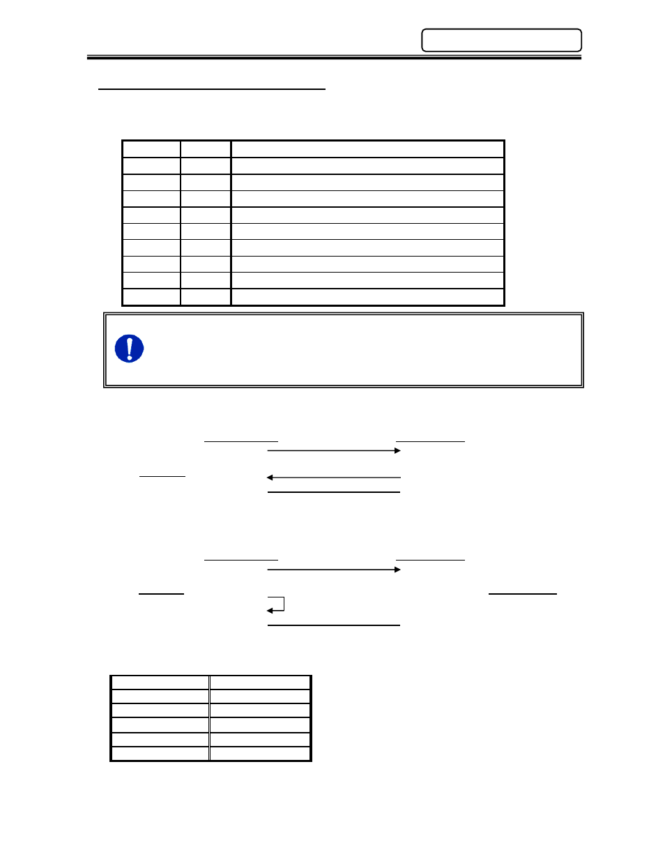
Connector:
DB-9P (Male)
Mating Connector: DB-9S (Female)
PIN No.
Signal
Signal Description
1
Not
Used
2
RXD
Not Used
3
TXD Output data for printer
4
DTR
ON output (always)
5
GND
Signal ground
6
Not
Used
7
RTS
ON output (always)
8
CTS Connects to DTR signals such as printers
9
Not
Used
The CTS signal needs to be activated in order for the press data to be output. If it
is not activated, the data will be stored in the output buffer (up to 16KB). Once the
buffer is full, the data will be overwritten in a First In-First Out (FIFO) process. The
CTS signal may be connected to the RTS signal if data is to be “dumped” at every
process.
1) Connection for confirming the DTR device
D-SUB 9 PIN D-SUB 25 PIN
TXD
3
3 RXD
RXD
2
CTS
8 20 DTR
GND
5 7 GND
2) Connection for output in any condition
D-SUB 9 PIN D-SUB 25 PIN
TXD
3
3 RXD
RXD
2
RTS
7
CTS
8 20 DTR
GND
5 7 GND
Communication Protocol
Data Bits
8
Error Control
No
Parity
No
Start Bits
1
Stop Bits
2
Speed
9600bps
DSP1500
DSP1500
Chapter 6: System Operation
Output Device