FEC DSP1500 (SAN3) User Manual
Page 113
PAGE 7-5
enFORCE
Operation Manual
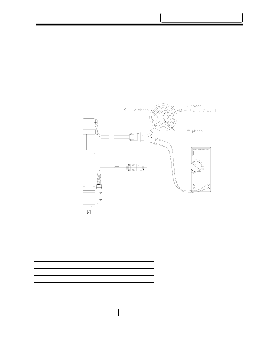
7.2.3 Motor
If doubts about the condition of the motor exist, the windings can be manually checked with an
Ohm meter. To check the motor, measure the winding's resistance and the isolation resistance.
• Power down the system.
• Disconnect the motor connector from the tool assembly.
• Measure the resistance between windings. (See Below)
• Measure the isolation resistance between each pair and the frame.
Insulation resistance: Using a megohmmeter, 500 VDC, 50 Mohms or more, test the insulation
resistance between the motor windings and the motor case. The values should register in
excess of 50 Mohms for each winding.
Motor Winding Resistance*
MOTOR SIZE Pins J - K
Pins K - L
Pins L - J
60W (M1)
15.6Ω
15.6Ω
15.6Ω
200W (M3)
1.6Ω
1.6Ω
1.6Ω
1500W (M4)
.9Ω
.9Ω
.9Ω
Resolver Winding Resistance
MOTOR SIZE
Pins A - B
Pins C - D
Pins E - F
60W (M1)
100 −115 Ω
90 − 100 Ω 90 − 100 Ω
200W (M3)
100 −115 Ω
90 − 100 Ω 90 − 100 Ω
1500W (M4)
30 − 40 Ω
50 − 65 Ω
50 − 65 Ω
Insulation Resistance
MOTOR SIZE
Pins J - K
Pins K - L
Pins L - J
60W (M1)
200W (M3)
1500W (M4)
More than 50 megohms at 500 VDC
Tolerance + / - 10%
Resolver windings should not
be “Open” or zero ohms.
Chapter 7: Maintenance & Inspection