External monitor (mon) signal connection – FEC DSP1500 (SAN3) User Manual
Page 52
PAGE 4-20
enFORCE
Operation Manual
4.9 MON. Signal (External Monitor Signal)
This auxiliary connector is used to output Load, Position, Current and Speed signals to external
equipment for monitoring purposes. This connection is not required for the system to operate.
enFORCE
outputs 1 digital pulse per 0.1mm moved distance and press proportionate to load by
the MON>OUT connectors. (There are some time differences in the distance pulse)
Mating Connector
Manufacture: Molex
Housing Part No.: 39-01-2065
Contact Part No.:
30-00-0047 (Qty.-6)
NO Signal Name
IN/OUT Description
1 LOAD OUT
OUT Load voltage Monitor Output full-scale load 2.5V
2
POSITION PULSE OUT Distance pulse Monitor Output TTL
3 POSITION
CW/CCW
OUT Advance/Return Monitor Output TTL
4 Current Monitor OUT -10V~+10V (10V=SAN40S=40A/ SAN80S=80A/ SAN120S=120A)
5
Speed Monitor
OUT -10V~+10V (10V = Maximum Speed)
6
GND
GND for Monitor Signal Output
LOAD OUT
- Load Voltage (Analog Voltage)
Monitor voltage represents zero load to full-scale load by an electric potential difference of
2.5V.
Home-position voltage is voltage measured when the press is stopped.
The Home position voltage is not 0V. (It may differ but the voltage is within
-2V to +2V)
Home position voltage of the same tool type differs as well.
Example: If the Home position voltage is –0.5V, the full-scale load voltage
is +2.0V and the voltage change (potential difference) is 2.5V.
*This signal will not output without a load transducer.
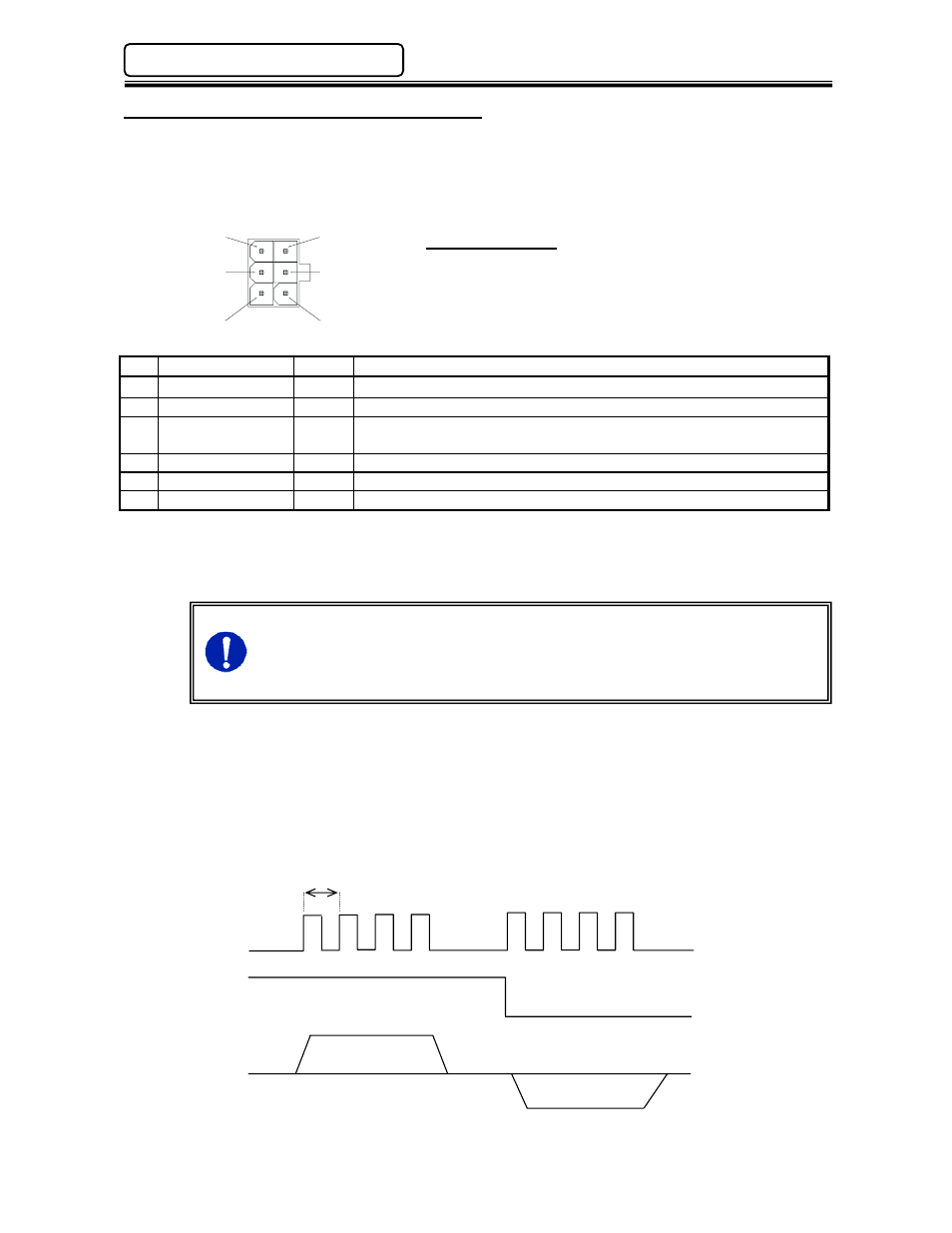
POSITION PULSE
- Distance Pulse:
(TTL
signal 0V or 5V)
Distance pulse is output at 1 pulse per 0.1mm. It slightly differs from the actual distance
moved.
POSITION CW/CCW
- Advance/Return Signal: (TTLsignal 0V or 5V)
HIGH signal is output on advance (clockwise revolution) and LOW signal is output on return
(counter-clockwise
revolution).
0.1mm
Distance Pulse
Advance/Return Signal
Advance Stop
Operating Condition Return
*This is based on the rotation direction of the motor so it may show “Advance” while returning
for tools with inverted motors.
6
3
5
4
2
1
Chapter 4: System Setup and Wiring